
Cleaning device and cleaning method for high-cleanliness ultrasonic material belt

A high cleanliness and cleaning device technology, applied in cleaning methods and utensils, cleaning methods using liquids, chemical instruments and methods, etc., can solve problems such as wear, cleaning effect decline, and mutual friction between them, so as to improve cleaning effect, The effect of controlling cleanliness

Inactive Publication Date: 2013-05-08
ZHANGJIAGANG ULTRASONIC & ELECTRIC
View PDF6 Cites 4 Cited by
  • Summary
  • Abstract
  • Description
  • Claims
  • Application Information

AI Technical Summary

Problems solved by technology

[0003] Because the traditional ultrasonic device is used to clean the material belt, in the actual operation process, because the material belt is a precision part, it is easy to cause mutual friction during the material belt receiving process, resulting in a certain amount of wear and affecting the product of cleaning the material belt. quality
In addition, traditional cleaning equipment uses long-section cleaning, that is, multiple sets of ultrasonic transducers are installed in one cleaning tank, which cannot control the cleanliness of the cleaning agent, resulting in a decline in cleaning effect

Method used


Image

  • Cleaning device and cleaning method for high-cleanliness ultrasonic material belt
  • Cleaning device and cleaning method for high-cleanliness ultrasonic material belt
  • Cleaning device and cleaning method for high-cleanliness ultrasonic material belt

Examples


Embodiment 1

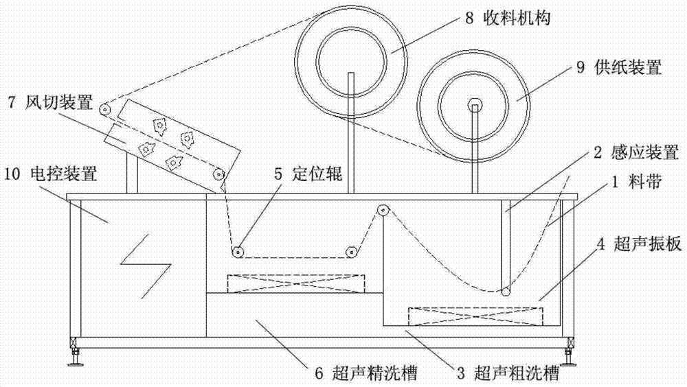
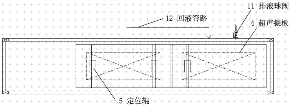
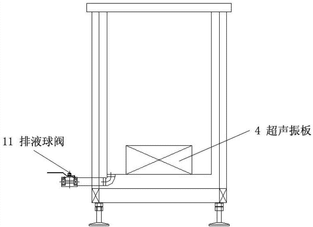
[0029] Such as Figure 1-Figure 3 As shown, after the material belt 1 enters the ultrasonic coarse cleaning tank 3, the induction device 2 is installed in the ultrasonic rough cleaning tank 3, the material belt 1 passes through the U-shaped induction device 2, and the material belt 1 passes in a U shape. This device adopts a unique The setting of two-stage cleaning tanks can greatly reduce the waste of cleaning agents and improve the smoothness of the material belt 1 after cleaning. The material strip 1 first enters the ultrasonic rough cleaning tank 3, and the bottom of the rough cleaning tank 3 is provided with an ultrasonic vibrating plate 4, and the ultrasonic vibrating plate 4 is treated with hard chrome plating, which greatly improves the service life of the vibrating plate. Then it enters the ultrasonic fine cleaning tank 6 through the positioning roller 5, and the ultrasonic fine cleaning tank 6 is also provided with an ultrasonic vibrating plate 4 at the bottom. The ...

Embodiment 2

[0031] On the basis of the above examples, if Figure 1-Figure 3 As shown, further, strip 1 is in the front view figure 1 Running from right to left, it enters the rough ultrasonic cleaning tank 3. The rough ultrasonic cleaning tank 3 uses SUS304 stainless steel plate as the tank body. Compared with other steel plates, such as SUS303 steel plate, SUS304 stainless steel plate has better corrosion resistance; Good ultrasonic transmission efficiency and corrosion resistance. An ultrasonic vibrating plate 4 is arranged at the bottom of the rough ultrasonic cleaning tank 3 . Ultrasonic vibrating plate 4 is made of SUS316L stainless steel. SUS316L stainless steel has better corrosion resistance than SUS304. Since SUS316L stainless steel contains 2-3℅ of molybdenum, it improves the resistance to reducing salts and various inorganic and organic acids and alkalis. , Corrosion resistance of salt. The vibration amplitude surface is treated with hard chromium plating. Since the workpie...

Embodiment 3

[0033] On the basis of the above examples, if Figure 1-Figure 3 As shown, further, due to the active force of the receiving mechanism 8, the material strip 1 enters the ultrasonic fine cleaning tank 6 through the positioning roller 5, and the same ultrasonic vibrating plate 4 in the ultrasonic rough cleaning tank 3 is arranged in the ultrasonic fine cleaning tank 6 . Its function and purpose are the same. This secondary cleaning setting can greatly improve the cleaning effect of the material belt 1, and prevent serious cleaning agent pollution caused by long-section cleaning, which affects the cleaning effect.


PUM


Abstract

The invention relates to a cleaning device for a high-cleanliness ultrasonic material belt. The cleaning device for the high-cleanliness ultrasonic material belt comprises a tank body, and an electric control device is hermetically arranged inside the tank body. The cleaning device for the high-cleanliness ultrasonic material belt is characterized in that an ultrasonic rough washing tank and an ultrasonic fine washing tank are arranged inside the tank body in a separated mode, ultrasonic vibrating plates are respectively arranged on the bottoms of the ultrasonic rough washing tank and the ultrasonic fine washing tank, a wind cutting device used for drying the material belt is arranged above the tank body, a positioning roller is arranged on the wind-cutting device in a connected mode, and a material collecting mechanism and a paper made paper supply device used for separating the material belt are arranged above the tank body. With the technical scheme of the cleaning device for the high-cleanliness ultrasonic material belt, the problem of mutual friction of the material belt in material collecting process is effectively solved, and no harm is done to the material belt. More importantly, the cleanliness of cleaning agents can be effectively controlled, and the cleaning effect of the material belt is improved.

Description

technical field [0001] The invention mainly relates to an industrial cleaning device, in particular to a high-cleanliness ultrasonic strip cleaning device and cleaning method. Background technique [0002] Ultrasonic cleaning is one of the most important applications of power ultrasound. The ultrasonic cleaning machine uses the cavitation effect, acceleration effect and straight-forward flow effect of ultrasonic waves in the liquid to directly and indirectly affect the liquid and dirt, so that the dirt layer is dispersed, Emulsification, stripping to achieve the purpose of cleaning. Among all cleaning methods, ultrasonic cleaning has the highest efficiency and the best effect. Because of its high cleaning efficiency and good quality, it is widely used in industry, national defense, medical and health and other fields. [0003] Because the traditional ultrasonic device is used to clean the material belt, in the actual operation process, because the material belt is a precisi...

Claims


Application Information

Patent Timeline
Patent Type & Authority Applications(China)
IPC IPC(8): B08B3/12
Inventor 陈宏
Owner ZHANGJIAGANG ULTRASONIC & ELECTRIC
Learn More