Unlock instant, AI-driven research and patent intelligence for your innovation.

Drive circuit, drive method of drive circuit and display device

a drive circuit and drive method technology, applied in the field of display drive technology, can solve the problems of poor contrast image, flickering, and short charge time of pixels,

Active Publication Date: 2020-02-20
HKC CORP LTD +1
View PDF2 Cites 4 Cited by
  • Summary
  • Abstract
  • Description
  • Claims
  • Application Information

AI Technical Summary

Benefits of technology

The present invention provides a drive circuit that uses multiple switch modules to control the connection of signal output lines with corresponding scan lines. These switch modules are controlled to be turned on or off by an upper scan line. This allows the circuit to charge pixels of successive rows with sufficient time, resulting in better contrast and reduced flickering. Thus, the technical effect of the invention is to improve the display quality of a display panel.

Problems solved by technology

In practical applications, during the process of charging, the pixels of the display area of the TFT-LCD have the problem that the pixels are charged insufficiently.
Under the situation that the frame period is constant, the scan time of each scan line is too short, so that the charge time of the pixels is too short.
The problem that the pixels are charged insufficiently results in poor contrast images and flickers.
This also causes the problem that the pixels are charged insufficiently results in poor contrast images and flickers.

Method used


Image

  • Drive circuit, drive method of drive circuit and display device
  • Drive circuit, drive method of drive circuit and display device
  • Drive circuit, drive method of drive circuit and display device

Examples


Embodiment Construction

[0021]Advantages and features of the inventive concept and methods of accomplishing the same may be understood more readily by reference to the following detailed description of embodiments and the accompanying drawings. The inventive concept may, however, be embodied in many different form and should not be construed as being limited to the embodiments set forth herein.

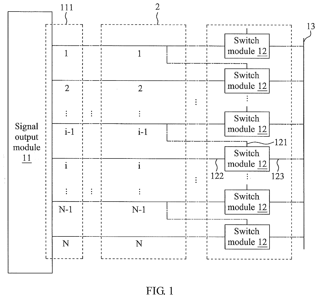
[0022]FIG. 1 is a schematic view of a drive circuit in accordance with an embodiment of the present invention. The drive circuit includes a signal output module 11 and a plurality of switch modules 12.

[0023]The signal output module 11 includes N output ends 111 for outputting gate drive signals step by step to N scan lines 2.

[0024]Each of the switch modules 12 corresponds to a corresponding one of the scan lines 2. A control end 121 of each switch module 12 is electrically connected with the i−1th scan line 2. A first connecting end 122 is electrically connected with the corresponding i-th scan line 2. A second conne...


PUM


Abstract

A drive circuit, a drive method of the drive circuit and a display device are provided. The drive circuit includes a signal output module, a first level signal output end; and a plurality of switch modules. The signal output module includes N output ends for outputting a gate drive signal step by step to N scan lines. The switch modules each correspond to one of the scan lines. A control end of the i-th switch module is electrically connected with the i−1th scan line. A first connecting end is electrically connected with the corresponding i-th scan line. A second connecting end is electrically connected with the first level signal output end. Wherein, N is a positive integer, and i is a positive integer greater or less or equal to N.

Description

CROSS-REFERENCE TO RELATED APPLICATION[0001]This application claims the benefit of China Patent Application No. 201710329014.1, filed on May 11, 2017, in the State Intellectual Property Office of the People's Republic of China, the disclosure of which is incorporated herein in its entirety by reference.FIELD OF THE INVENTION[0002]The present invention relates to the display drive technology, and more particularly to a drive circuit, a drive method of the drive circuit and a display device.BACKGROUND OF THE INVENTION[0003]A thin film transistor liquid crystal display (TFT-LCD) is one of panel displays on the market, and it has become an important display platform of modern IT and video products. The drive principle of the TFT-LCD is that a system board of the display transmits an R / G / B compression signal and a control signal to a connector of a printed circuit board (PCB) through the wiring. After the data signal and the control signal are processed by a timing controller of the prin...

Claims


Application Information

Patent Timeline
IPC IPC(8): G09G3/36
CPCG09G3/3677G09G3/3696G09G3/3648G09G3/20
Inventor CHEN, YU-JEN
Owner HKC CORP LTD