Image synthesis system

a technology of image synthesis and synthesis system, applied in the field of image synthesis system, can solve the problems of image blur, low radiometric performance, and reduction of the available area for light capture, and achieve the effect of reducing the residual perspective error

Active Publication Date: 2020-02-20
SPOOKFISH INNOVATIONS
View PDF10 Cites 4 Cited by
  • Summary
  • Abstract
  • Description
  • Claims
  • Application Information

AI Technical Summary

Benefits of technology

[0035]In an embodiment, the system is arranged to define multiple synthetic global shutter image portions based on the synthetic global shutter image, and to select a different position and pose for each synthetic global shutter image portion that reduces a residual perspective error for the synthetic global shutter image portion. The multiple synthetic global shutter image portions may be multiple synthetic global shutter image strips or tiles.

Problems solved by technology

However, such techniques typically cause image blur.
However, such global shutter sensors require significant circuitry that results in a reduction in the available area for light capture, have relatively low radiometric performance, and require relatively high power consumption, which ultimately reduces maximum frame rates and increases costs.
However, with a RS-type camera system under motion each frame does not have a single position and pose.
Rolling shutter (RS)-type sensors also result in image distortion when the sensor or object in the image frame is under motion during exposure, because different scanlines in the sensor are exposed at different times.
Firstly, motion of the camera system during exposure of a frame will induce skew and wobble distortions, due to translation and rotation of the camera optical centre during rolling shutter readout.
Secondly, if the scene is not flat, as with a typical real-world scene, a residual perspective error will remain due to a change in parallax during rolling shutter readout.
Consequently, RS-type sensors have not been used to any great extent in aerial survey camera systems.

Method used


Image

  • Image synthesis system
  • Image synthesis system
  • Image synthesis system

Examples


Embodiment Construction

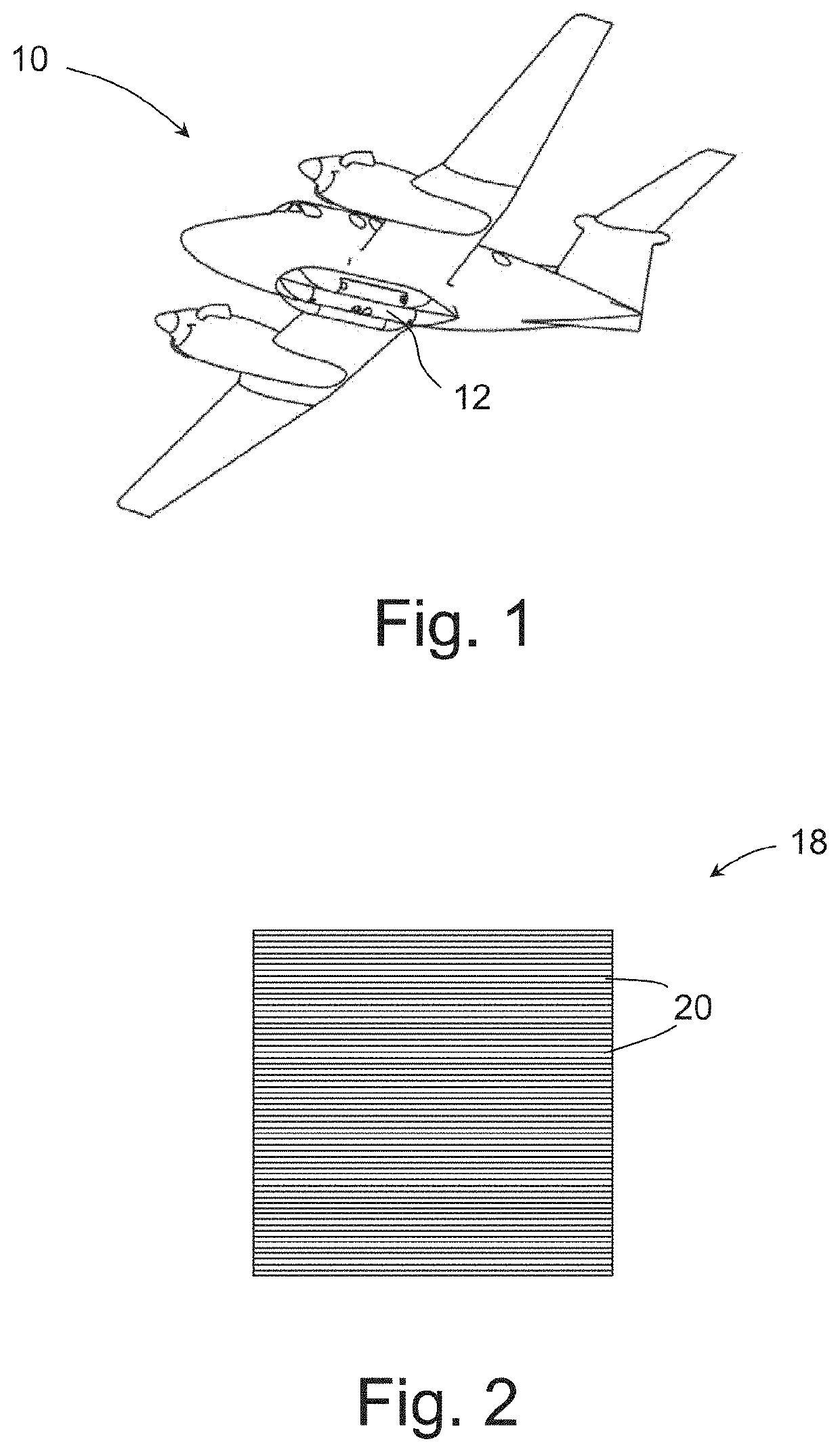
[0053]Referring to FIG. 1 of the drawings, a survey aircraft 10 with mounted aerial camera system 12 is shown.

[0054]The aerial camera system 12 in this example may include a stationary or movable camera assembly, for example arranged to rotate about a central longitudinal axis.

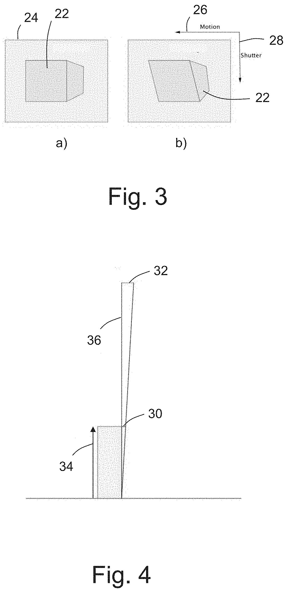
[0055]The camera assembly includes at least one RS sensor 18 of the type shown in FIG. 2.

[0056]In this example, the lens assembly 30 has a focal length of about 376 mm, although other focal lengths are envisaged, such as 1800 mm.

[0057]In an example camera assembly wherein a camera captures images as the camera rotates about a central longitudinal axis, image compensation arrangements may be provided to compensate for forward and across track movement, for example as disclosed in co-pending International Patent Application No. PCT / AU2015 / 000606.

[0058]The camera system 12 is arranged such that the field of regard (FoR) is directed generally vertically downwards in order to capture images of the ground directly b...


PUM


Abstract

An image synthesis system is disclosed for synthesizing a global shutter image based on a rolling shutter image. The rolling shutter image is captured by an aerial camera system having at least one rolling shutter camera and the rolling shutter image has a plurality of scanlines, the scanlines having associated different position and pose information. The image synthesis system is arranged to project a rolling shutter image captured by a rolling shutter camera to object space by projecting each scanline of the rolling shutter image using position and pose information associated with the scanline, and subsequently from object space to a synthetic global shutter image.

Description

FIELD OF THE INVENTION[0001]The present invention relates to an image synthesis system for use in an aerial survey system of the type that uses rolling shutter image sensors.BACKGROUND OF THE INVENTION[0002]It is known to provide an aerial camera system that is arranged to capture ground images from a survey aircraft. Typically, as shown in FIG. 1, the aerial camera system 12 is mounted to an underside portion of the survey aircraft 10 and ground images are captured as the survey aircraft 10 moves along defined flight lines. The system is arranged to capture multiple images for each point on the ground, which enables a photogrammetric solution, typically a bundle adjustment process, to be applied to the captured images in order to determine a best case solution for interior and exterior orientation information associated with each camera used and the images captured by each camera. The solution produced by the bundle adjustment process may then be used to produce nadir and / or obliqu...

Claims


Application Information

Patent Timeline
Patent Type & Authority Applications(United States)
IPC IPC(8): H04N5/232H04N5/353
CPCH04N5/23258H04N5/353H04N5/23267H04N25/531H04N23/6812H04N23/683H04N25/53
Inventor COPE, SIMONKOVESI, PETERXIAO, ZIANZONG
Owner SPOOKFISH INNOVATIONS
Why Eureka
Try Eureka