Pneumatic tire

a pneumatic tire and tire body technology, applied in the field of pneumatic tires, can solve the problems of cavernous resonance, vibration of cloth, and noise in the interior of the tire, and achieve the effect of reducing cavernous resonance and improving productivity

Inactive Publication Date: 2020-02-27
TOYO TIRE & RUBBER CO LTD
View PDF0 Cites 2 Cited by
  • Summary
  • Abstract
  • Description
  • Claims
  • Application Information

AI Technical Summary

Benefits of technology

[0023]According to the pneumatic tire of the present invention, reducti...

Problems solved by technology

Cavernous resonance may produce noise in an interior of the vehicle, wherefore reduction of cavernous resonance has been attempted.
In t...

Method used


Image

  • Pneumatic tire
  • Pneumatic tire
  • Pneumatic tire

Examples


Embodiment Construction

[0032]Embodiments of the present invention will be hereinafter described with reference to the accompanying drawings.

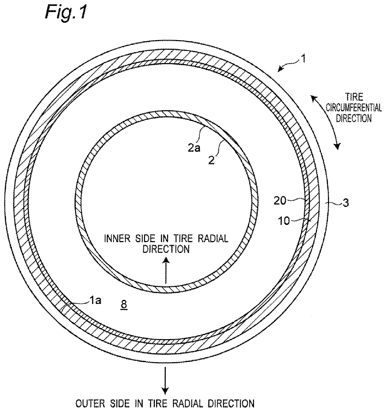
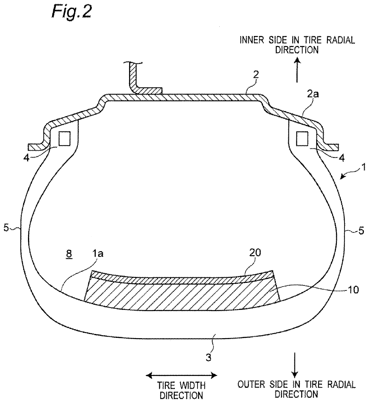
[0033]FIG. 1 is a longitudinal cross-sectional view of a pneumatic tire according to a first embodiment of the present invention, while FIG. 2 is a transverse cross-sectional view of the pneumatic tire according to the first embodiment of the present invention. As shown in FIGS. 1 and 2, a pneumatic tire 1 made of rubber according to the first embodiment of the present invention is assembled to a wheel 2 to produce a vehicle wheel constituted by the pneumatic tire 1 and the wheel 2. The pneumatic tire has an annular shape. A tire interior (inner cavity) 8 having an annular shape is formed by a tire inner surface 1a of the pneumatic tire 1 and an outer surface of a rim 2a of the wheel 2.

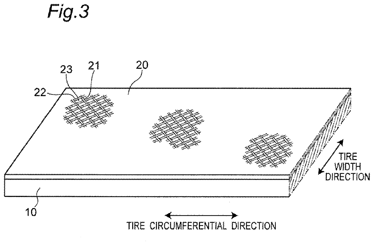
[0034]As shown in FIG. 2, the pneumatic tire 1 includes: a tread portion 3 located on an outer side in a tire radial direction and in contact with a road surface; bead portions 4 provid...


PUM


Abstract

A pneumatic tire includes: a sound absorbing member that is made of sponge, attached to a tire inner surface of a tread portion, and extends in a tire circumferential direction; and a cloth that is attached to a tire radially inner surface of the sound absorbing member, and extends in the tire circumferential direction.

Description

CROSS-REFERENCE TO RELATED APPLICATION[0001]This application claims priority of Japanese Patent Application No. 2018-155601 filed on Aug. 22, 2018, the content of which is incorporated herein by reference.BACKGROUND OF THE INVENTIONTechnical Field[0002]The present invention relates to a pneumatic tire.Related Art[0003]It is known that air inside a tire generates cavernous resonance with vibration caused from a tire contact surface when a vehicle travels on a rough road surface or passes through a joint of a road surface, or in other situations. Cavernous resonance may produce noise in an interior of the vehicle, wherefore reduction of cavernous resonance has been attempted.[0004]For example, JP 2017-202790 A discloses a pneumatic tire which reduces cavernous resonance by attaching a plate-shaped member to a tire inner surface of a tread portion. The plate-shaped member includes a plurality of through holes and a plurality of slits extending in a tire circumferential direction. A plu...

Claims


Application Information

Patent Timeline
IPC IPC(8): B60C19/00
CPCB60C19/002B60C5/002B60C5/007
Inventor SAKAKIBARA, KAZUHIRO
Owner TOYO TIRE & RUBBER CO LTD
Why Eureka
Try Eureka