Wind-up system and method for winding-up a strip

a winding system and strip technology, applied in the field of winding systems and methods for winding strips, can solve the problems of difficult to accurately deposit the elongated element on the collection reel of different specifications, unpredictability of the conveyor of the feeding device, and unpredictability of the length of the elongated element, etc., to achieve convenient and/or rapid alternate, reduce the effect of space consumption

Active Publication Date: 2020-02-27
VMI HOLLAND BV
View PDF0 Cites 2 Cited by
  • Summary
  • Abstract
  • Description
  • Claims
  • Application Information

AI Technical Summary

Benefits of technology

[0038]In an embodiment thereof the wind-up system comprises a second supply member extending in-line with the first supply member above the first work station for receiving and guiding the strip over said first work station when the picked-up leading end of the strip is placed at a placement position within the second guide area of the second work station. The strip can thus be guided overhead the first work station, thereby effectively bypassing said first work station so that the full first collection reel can be replaced without interfering with the winding in the second work station.
[0039]In an alternative embodiment the first work station and the second work station are arranged side-by-side in a direction transverse to the supply direction. By arranging the work stations side-by-side, the wind-up system can be designed to consume less space on the factory floor and / or to be more compact.
[0040]In an embodiment thereof the first work station, the second work station or both are at an oblique angle with respect to the supply direction. In such a configuration, e.g. a Y or V configuration, the pick-and-place member can easily and / or quickly alternate between the work stations by rotating over an angle into alignment with one of the respective work stations.

Problems solved by technology

It has been found that elongated elements, in particular strips for use in breaker plies for tires, behave unpredictably on the conveyors of the feeding device.
Because the specifications of the collection reel are typically in the clients' domain, it may be difficult to accurately deposit the elongated element onto collection reels of different specifications.
This is a potentially hazardous operation, in particular when the elongated element has sharp edges, e.g. due to steel wires.

Method used


Image

  • Wind-up system and method for winding-up a strip
  • Wind-up system and method for winding-up a strip
  • Wind-up system and method for winding-up a strip

Examples


first embodiment

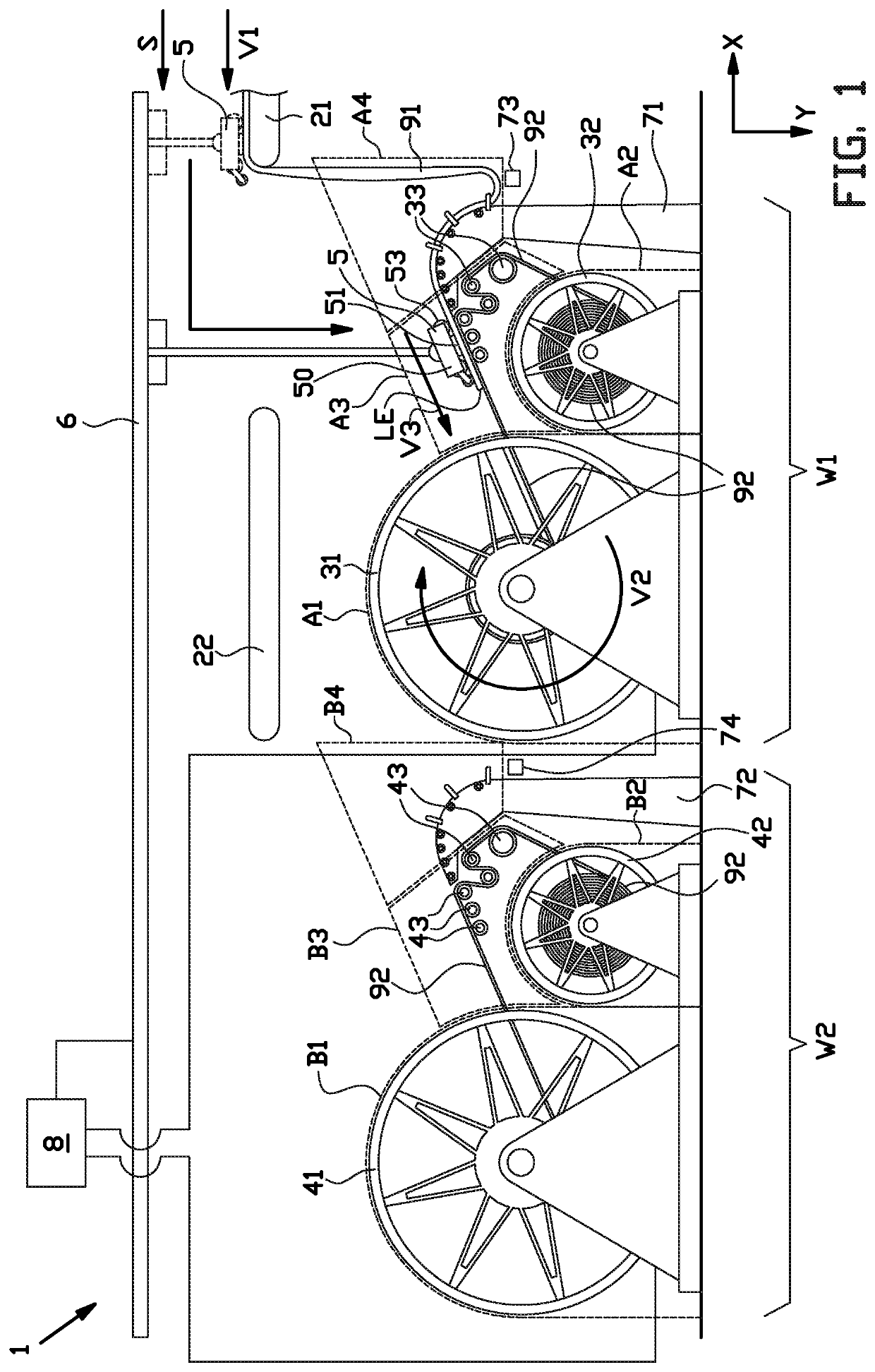
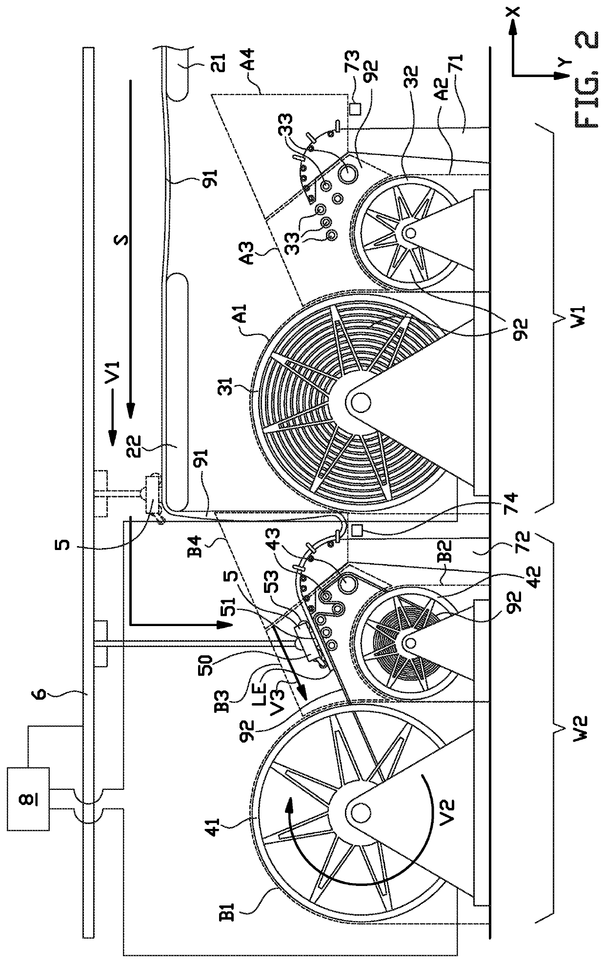
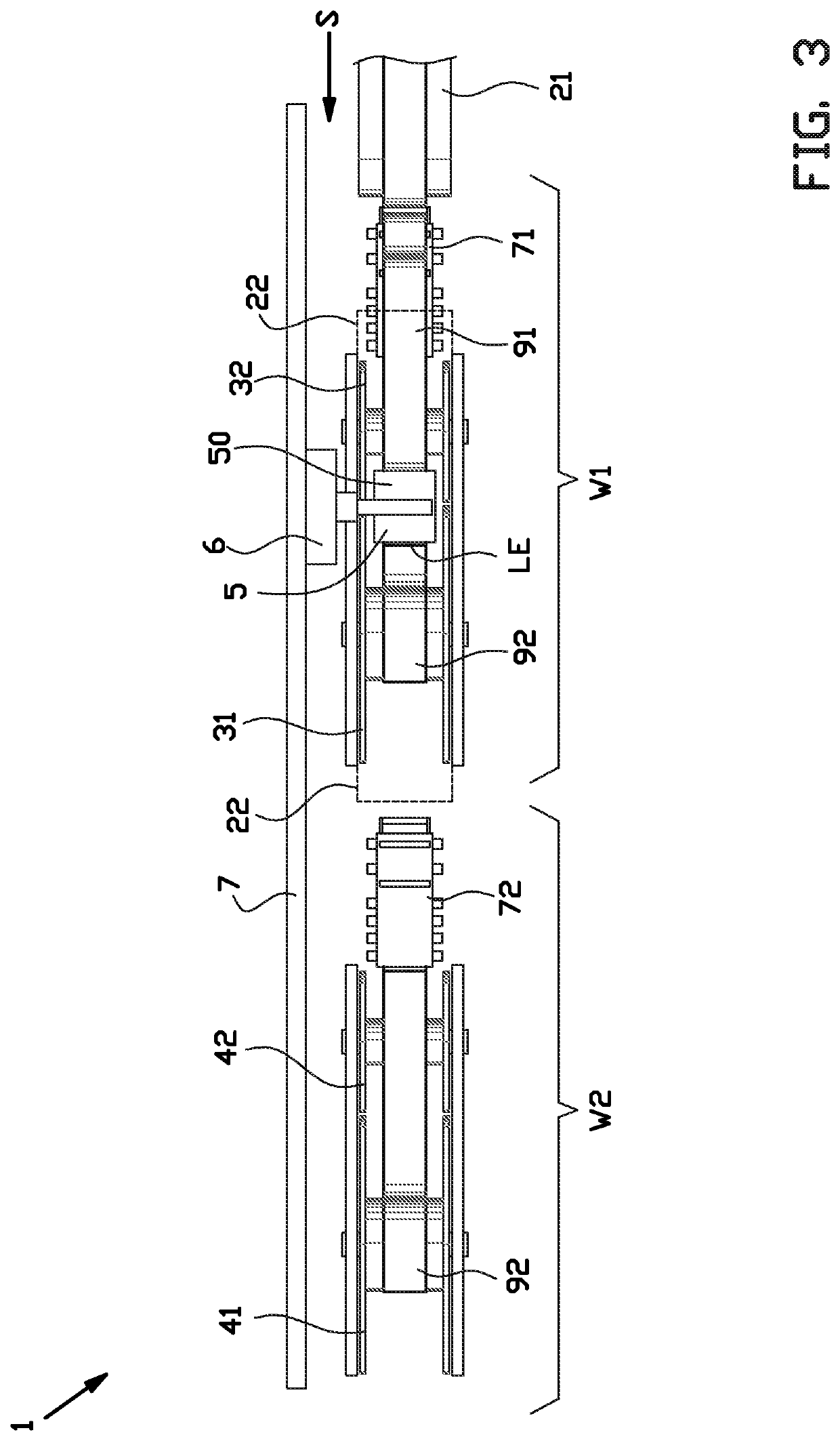
[0067]As shown in FIGS. 1 and 2, the wind-up system 1 comprises a first work station W1 and a second work station W2. The strip 91 can be alternately wound-up in each of said work stations W1, W2 to allow handling of a previously wound-up strip 91 in the inactive work station W1, W2. As best seen in FIGS. 3 and 4, the work stations W1, W2 according to this first embodiment of the invention are arranged in tandem or in-line.

[0068]In this exemplary embodiment, the wind-up system 1 comprises a first supply member 21 and a second supply member 22 for supplying the strip 91 to the first work station W1 and the second work station W2, respectively, in a supply direction S. As shown in FIGS. 1 and 3, the first supply member 21 is located above and directly upstream of the first work station W1 with respect to the supply direction S. As shown in FIGS. 2 and 4, the second supply member 22 is located overhead the first work station W1 and directly upstream of the second work station W2. In th...

third embodiment

[0101]FIG. 11 shows a further alternative pick-and-place member 205 according to the invention. The alternative pick-and-place member 205 differs from the previously discussed pick-and-place member as shown in FIGS. 9 and 10 in that it is provided with an additional retaining element 257 at the deflection roller 255. In particular, said additional retaining element 257 is arranged at or inside the deflection roller 255 to retain the strip to the deflection roller 255. Hence, the retaining element 257 at or in the deflection roller 255 can cooperate with the one or more retaining elements 51 at the head 50 to securely retain the strip. This is particularly useful when the strip has a relatively long leading end, in which case said leading end can be retained more reliably. In this particular example, the additional retaining element 257 is a magnet, preferably a permanent magnet. Alternatively, the additional retaining element 257 may be a vacuum element. Preferably, the magnet is lo...

fourth embodiment

[0102]FIG. 12 shows a further alternative wind-up system 301 according to the invention in which a third work station W3 is added together with a third supply member 23 overhead the second work station W2 to bypass said second work station W2. Further stations may be added in a similar manner. The third work station W3 may for example be a station for collecting scrap or a station for collecting different strips or tire components.


PUM

PropertyMeasurementUnit
areaaaaaaaaaaa
speedaaaaaaaaaa
degrees of freedomaaaaaaaaaa

Abstract

Disclosed is a wind-up system and a method for winding-up a strip. The wind-up system includes a first work station and a first supply member for supplying the strip to said first work station. The first work station includes a first collection area for holding a first collection reel to collect and wind-up the strip; a first liner area for holding a first liner reel to unwind a liner, and a first guide area extending from the first liner area into the first collection area, wherein the unwound liner is unwound from the first liner reel through the first guide area onto the first collection reel. The wind-up system further includes a pick-and-place member for picking-up a leading end from the first supply member and for placing the picked-up leading end of the strip onto the liner within the first guide area.

Description

BACKGROUND[0001]The invention relates to a wind-up system and method for winding-up a strip.[0002]US 2012 / 0248651 A1 discloses a method and apparatus for controlling the winding of an elongated element onto a collection reel with the interposition of a service fabric. The apparatus features a first work station and a second work station substantially identical to the first work station and arranged downstream of said first work station. The apparatus is arranged for feeding the elongated element alternately on the collection reel of the first work station or on the collection reel of the second work station, allowing the collection and the discharge of a collection reel while the elongated element and the service fabric are wound on the other collection reel. The apparatus is provided with a feeding device having a first conveyor belt close to the collection reel and a second conveyor belt operatively arranged between the first conveyor belt and the collection reel. The second conve...

Claims


Application Information

Patent Timeline
Patent Type & Authority Applications(United States)
IPC IPC(8): B65H19/22B65H18/10
CPCB65H19/2207B65H2301/414324B65H2301/44332B65H18/10B65H2801/93B65H23/038B65H19/22B65H2301/4127
Inventor HAMMER, JAAPMEIJERS, PIETER CORNELIS
Owner VMI HOLLAND BV
Why Eureka
Try Eureka