Supercharge Your Innovation With Domain-Expert AI Agents!
Control method for converting time-varying system into time-invariant system
Active Publication Date: 2020-02-27
GUANGDONG UNIV OF TECH
View PDF0 Cites 0 Cited by
Summary
Abstract
Description
Claims
Application Information
AI Technical Summary
This helps you quickly interpret patents by identifying the three key elements:
Problems solved by technology
Method used
Benefits of technology
The patent aims to provide a control method for converting a time-varying system into a time-invariant system by means of compensation. This helps to eliminate the effects of parameters changes and improve the stability of the linear control system. The technical solution considers the nth derivative of the state variable as the quantity to be determined, and the (n−1)th order to the 0th derivative of the state variables are all known quantities. By using double compensation by measured and estimated disturbances, and the extended state observer (ESO) further compensates the uncertain part of the model, the time-varying system is transformed into a time-invariant system and the control system is equivalent to a constant system with constant parameters. This eliminates the effects of parameter changes and improves the linear control system performance. The change regulation between the equivalent control quantities to output remains constant, eliminating the effects of parameter changes. The patent simplifies the original algorithm to the active disturbance rejection control algorithm of ESO disturbance estimation compensation when there is no particular large total disturbance bandwidth.
Problems solved by technology
However, when the model parameters change, the state changing rate will also change after the same control quantity acts on the control object, which makes the control system performance worse.
Although the fuzzy, intelligent and robust control methods can improve the control system performance to a certain extent, it is difficult to apply them in high-speed precision motion control for the complexity of the algorithm.
By considering the model error and the external disturbance as a whole, the disturbance can be suppressed to some extent, hut the active disturbance rejection controlalgorithm will be affected by the bandwidth of the observer and the bandwidth of the control system, which leads to a lot of trouble in application.
Method used
Image
Click on the blue label to locate the original text in one second.
Reading with bidirectional positioning of images and text.
Examples
embodiment 1
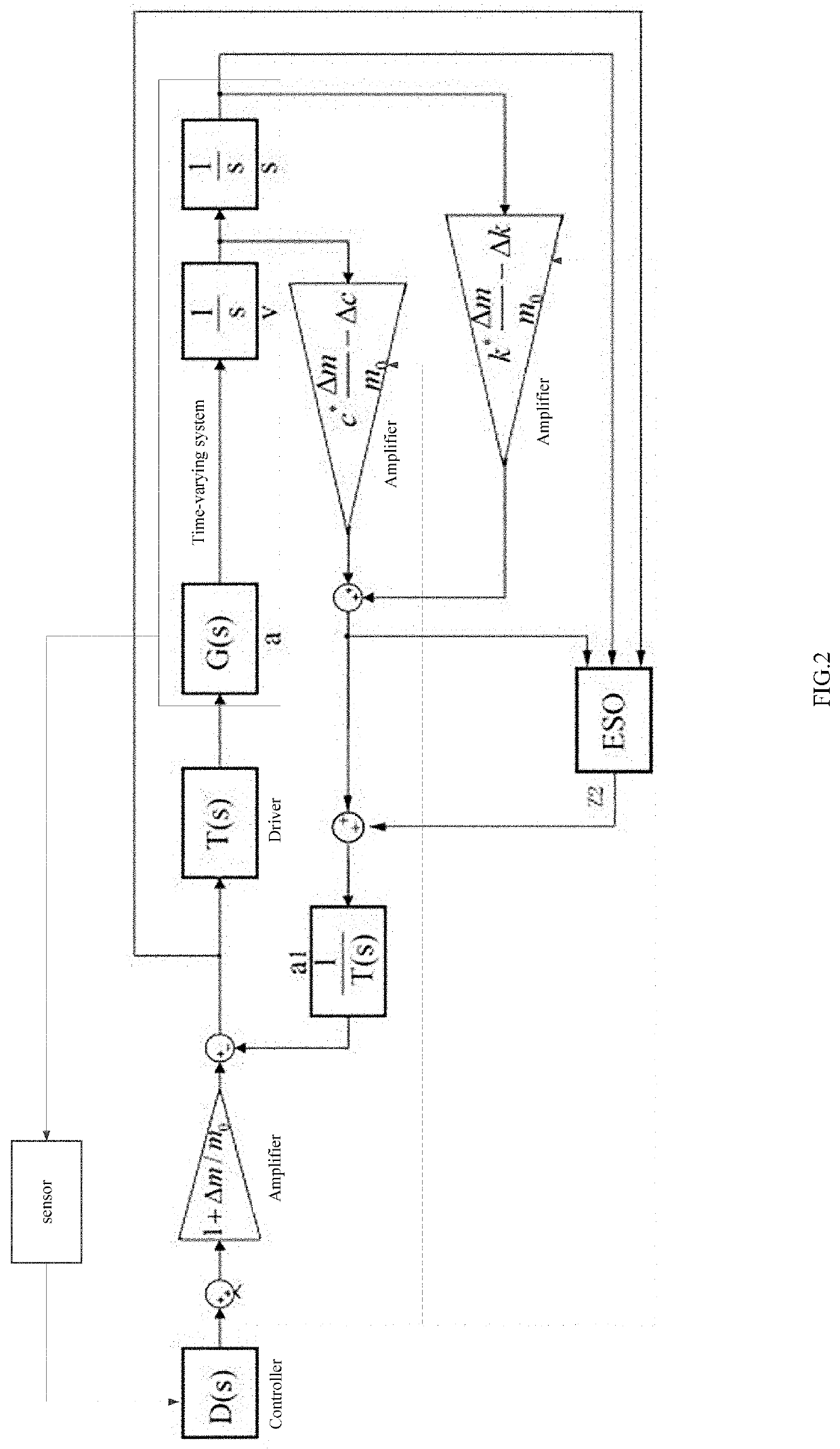
[0044]Referring to FIG. 2, the embodiment in the present invention takes a second-order system generally applied in mechanical engineering as an example, and a specific expression of the control system is:
m0{circumflex over (x)}(t)+c0x(t)+k0x(t)=u0(t) (1)
[0045]When a parameter of the controlled object (time-varying system) changes, the specific expression will become:
(m0+Δm){umlaut over (x)}(f)+(c0+Δc){dot over (x)}(t)+(k0+Δk)x(t)=u0(t) (2)
[0046]Since a control quantity u0(t) is obtained according to a deviation and is not directly related to the parameter of the controlled object, the changes of the parameter will lead to changes in the speed of the state change. In order to keep the speed of the state change unchanged, the control quantity needs to be compensated.
[0048]Organize the above formula to get the following expression:
(m0+Δm)x¨(t...
embodiment 2
[0056]The second order system of dual-mechanical arm is taken as an example in the present invention, the equation expression of specific joint control, is:
J1{umlaut over (θ)}1B1{dot over (θ)}=T1 (5)
[0057]The changes of the joint pose lead to the changes of the inertia of joint 1, the expression is:
(J1+ΔJ1){umlaut over (θ)}1+B1θ=T1 (6)
[0058]By multiplying both sides of the original model by
J1+ΔJ1J1,
the following expression can be obtained:
J1J1+ΔJ1J1θ¨1+B1J1+ΔJ1J1θ.=J1+ΔJ1J1T1(7)
[0059]Organize the expression (7) into a model with a parameter changed to obtain the following expression:
(J1+ΔJ1)θ¨1+B1θ.=J1+ΔJ1J1T1-B1ΔJ1J1θ.(8)
[0060]The value of AB in second order system model of dual-mechanical arm in the embodiment is 0.
[0061]As can be seen in expression (8), the compensation part of the measured disturbance is
-B1ΔJ1J1θ..
[0062]By adopting extended state observer, assign b the value
J1J1+ΔJ1
to further compensate the disturbances.
[0063]The second order ESO which could estimates the sp...
PUM
Abstract
A control method for converting time-varying system into a time-invariant system, comprises: using (n−1)th to 0th order signals of an nth-order time-varying, system as feedback to set up a closed loop control for the time-varying system; acquiring real-time values of the coefficients in each order of the time-varying system through a sensor, and calculating variations between the real-time values and the initial values of the coefficients in each order through a controller; amplifying and summing the parameters of every order to obtain a measured disturbance; inputting the measured disturbance, a control signal from a controller and an nth-order signal into an extended state observer through to estimate the rest disturbance; summing up the measured and estimated disturbances to obtain total disturbances; and adjusting the above parameters in each order through the controller to convert the time-varying system into the tune-invariant system.
Description
CROSS-REFERENCE TO RELATED APPLICATIONS[0001]This application is claims priority to Chinese Patent Application No. 201810966248.1 with a filing date of Aug. 23, 2018. The content of the aforementioned application, including any intervening amendments thereto, is incorporated herein by reference.TECHNICAL FIELD[0002]The disclosure relates to the technical field of automatic control, and particularly to a method for converting lime-varying system into time-invariant system.BACKGROUND OF THE PRESENT INVENTION[0003]More than 90% of the control systems in the industry adopt the PID (Proportional-Integral-Derivative) control algorithm. For time-varying systems, the PID control algorithm can obtain excellent control effects after adjusting parameter. However, when the model parameters change, the state changing rate will also change after the same control quantity acts on the control object, which makes the control system performance worse. Although the fuzzy, intelligent and robust contro...
Claims
Application Information
Patent Timeline
Application Date:The date an application was filed.
Publication Date:The date a patent or application was officially published.
First Publication Date:The earliest publication date of a patent with the same application number.
Issue Date:Publication date of the patent grant document.
PCT Entry Date:The Entry date of PCT National Phase.
Estimated Expiry Date:The statutory expiry date of a patent right according to the Patent Law, and it is the longest term of protection that the patent right can achieve without the termination of the patent right due to other reasons(Term extension factor has been taken into account ).
Invalid Date:Actual expiry date is based on effective date or publication date of legal transaction data of invalid patent.