Supercharge Your Innovation With Domain-Expert AI Agents!

Structure of electrical connector

Inactive Publication Date: 2017-10-03
ALLSMARTLITE TECH CO LTD
View PDF24 Cites 5 Cited by
  • Summary
  • Abstract
  • Description
  • Claims
  • Application Information

AI Technical Summary

Benefits of technology

[0004]An object of the present invention is to increase widths and thicknesses of grounding terminals and power terminals to predetermined values in order to satisfy the need for a large electrical current while preventing noise interference.
[0006]The upper grounding terminal assembly, the upper power terminal assembly, the lower grounding terminal assembly, and the lower power terminal assembly comprise soldering sections defined at one end thereof, each of the soldering sections having a width between 0.35 mm and 0.45 mm and a thickness between 0.1 mm and 0.2 mm, an extension sections defined at one side of each of the soldering sections, each of the extension sections having a width between 0.35 mm and 0.45 mm and a thickness between 0.1 mm and 0.2 mm, and a contact section defined at one side of each of the extension sections that is opposite to each of the soldering sections, each of the contact sections having a width between 0.285 mm and 0.295 mm and a thickness between 0.1 mm and 0.2 mm. Consequently, the volume or size of each grounding terminal assembly and power terminal assembly is increased to increase electrical current loading capacity thereof for suiting the need for supply of a large electrical current and reducing noise interference. As such, the drawbacks of the conventional high-frequency connectors that the electrical current loading capacity is insufficient and noise interference is severe can be overcome to achieve the advantages of suiting the need of supply of large electrical current and preventing noise interference.

Problems solved by technology

A conventional high-speed connector comprises metal conductors that are arranged to be very close, spatially, to each other so that capacitive coupling would occur during the transmission of signals and thus increasing interference with the transmission of the signals and lowering stability of signal transmission.
In addition, impedance matching is necessary between a high-speed transmission interface and a system main board interface, otherwise signal reflection would occur, leading to loss, deformation, and distortion of electronic signals, eventually making bandwidth and quality of electronic signals not reaching desired levels.
Further, recently, portable electronic products have been demanding increased amounts of power consumption.
However, the conventional high-frequency connector bears electrical current loading that has been long kept at a fixed level, leading to insufficient supply of electrical power or slow transmission of electrical power.

Method used


Image

  • Structure of electrical connector
  • Structure of electrical connector
  • Structure of electrical connector

Examples


Embodiment Construction

[0015]The following descriptions are exemplary embodiments only, and are not intended to limit the scope, applicability or configuration of the invention in any way. Rather, the following description provides a convenient illustration for implementing exemplary embodiments of the invention. Various changes to the described embodiments may be made in the function and arrangement of the elements described without departing from the scope of the invention as set forth in the appended claims.

[0016]Referring to FIGS. 1-5, an embodiment of an electrical connector is shown, which as shown for illustration and explanation, is a female connector that meets the specification of Universal Serial Bus (USB) 3.1 Type-C.

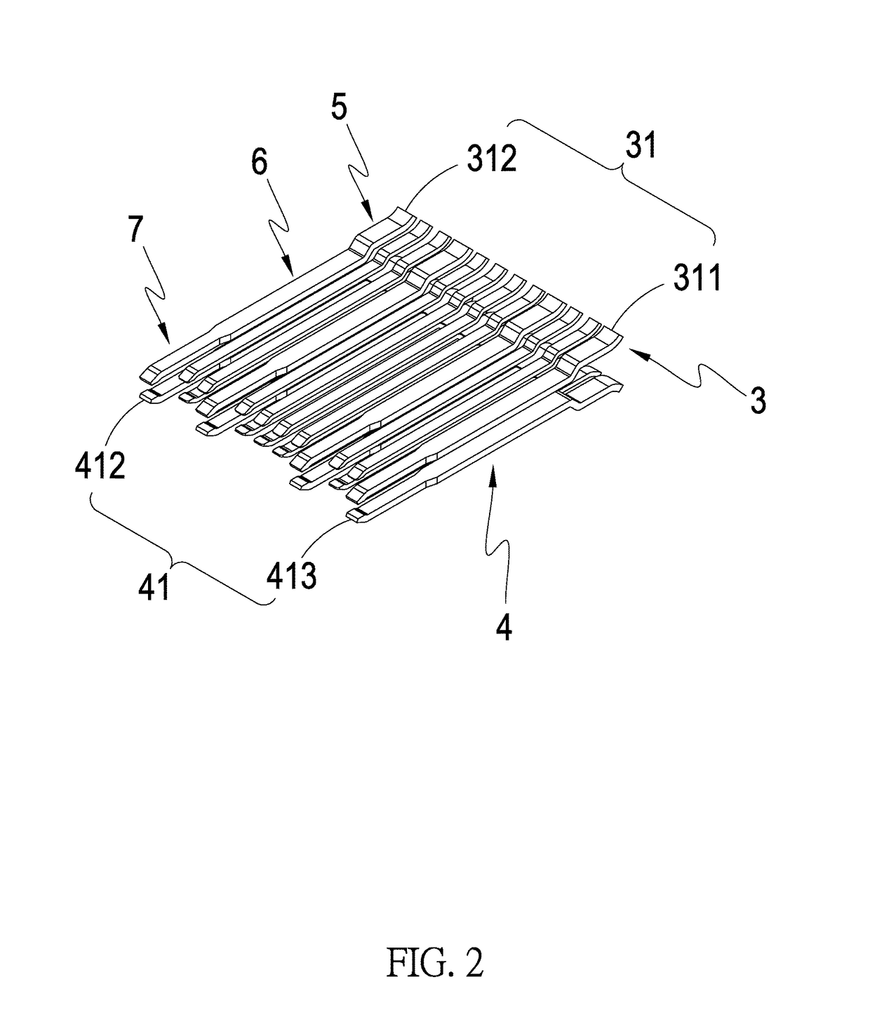
[0017]The present invention generally comprises a shielding enclosure 1, at least one insulation assembly 2, an upper transmission conductor assembly 3, and a lower transmission conductor assembly 4. The insulation assembly 2 is arranged inside the shielding enclosure 1. The upper ...


PUM


Abstract

Disclosed is an improved structure of an electrical connector, which includes an upper transmission conductor assembly including an upper grounding terminal assembly and an upper power terminal assembly; and a lower transmission conductor assembly including a lower grounding terminal assembly and a lower power terminal assembly, each of which defines soldering sections, extension sections, and contact sections. The soldering sections have a width between 0.35 mm and 0.45 mm and a thickness between 0.1 mm and 0.2 mm. The extension sections have a width between 0.35 mm and 0.45 mm and a thickness between 0.1 mm and 0.2 mm. The contact sections have a width between 0.285 mm and 0.295 mm and a thickness between 0.1 mm and 0.2 mm. As such, a need for supply of a large electrical current can be satisfied and noise interference can be prevented.

Description

TECHNICAL FIELD OF THE INVENTION[0001]The present invention relates generally to an improved structure of an electrical connector, which suits the need for supply of a large electrical current and also eliminates noise interference.DESCRIPTION OF THE PRIOR ART[0002]A conventional high-speed connector comprises metal conductors that are arranged to be very close, spatially, to each other so that capacitive coupling would occur during the transmission of signals and thus increasing interference with the transmission of the signals and lowering stability of signal transmission. In addition, impedance matching is necessary between a high-speed transmission interface and a system main board interface, otherwise signal reflection would occur, leading to loss, deformation, and distortion of electronic signals, eventually making bandwidth and quality of electronic signals not reaching desired levels.[0003]Further, recently, portable electronic products have been demanding increased amounts ...

Claims


Application Information

Patent Timeline
IPC IPC(8): H01R13/6471H01R13/6581H01R24/60H01R13/42H01R107/00
CPCH01R13/6471H01R24/60H01R13/6581H01R13/42H01R2107/00
Inventor WANG, XIAOPINGPERNG, MING-HANLAI, CHIEN-HSING
Owner ALLSMARTLITE TECH CO LTD
Features
  • R&D
  • Intellectual Property
  • Life Sciences
  • Materials
  • Tech Scout
  • Unparalleled Data Quality
  • Higher Quality Content
  • 60% Fewer Hallucinations
Learn More