Safety device for retraction of a needle and guidewire for medical procedures and method of use

Active Publication Date: 2020-03-12
REDSMITH INC
View PDF0 Cites 1 Cited by
  • Summary
  • Abstract
  • Description
  • Claims
  • Application Information

AI Technical Summary

Benefits of technology

[0018]An alternative aspect eliminates the passive component of retraction, and allows for complete active retraction controlled by the user. On the undersurface of the longitudinal member of the retraction frame is a rack that communicates with a compound gear also housed within the frame. This compound gear also communicates with a longitudinally oriented rack that is contained within the lower rail insert. When the frame is retracted through the more distal portion of the housing that does not contain this longitudinally oriented rack, the frame and the slide tab move in synchrony with about a 1:1 distance ratio. When the rack reaches the porti

Problems solved by technology

Once the needle and guidewire have traversed the skin and contact the patient's tissues and bodily fluids, both components pose a risk to healthcare workers.
Until properly disposed within a biohazard sharps container, these devices carry a risk of infecting the healthcare worker through many established modes of transmission.
Furthermore, these devices could contaminate other nearby surfaces, equipment, and other fomites, which could, in turn, transmit infections to other patients through hospital acquired (or associated) infections (HAIs).
These HAIs are of paramount concern to healthcare facilities and are recognized as a serious cause of morbidity and mortality.
Many devices with integrated safety components are cumbersome to use, which may interfere with the ease of use of a particular device, or may even increase the risk of improper catheter placement.
In others, once the safety mechanism is triggered, it is no longer possible to revert to the original configuration, and therefore the needle is no longer available if needed for a subsequent portion of the

Method used


Image

  • Safety device for retraction of a needle and guidewire for medical procedures and method of use
  • Safety device for retraction of a needle and guidewire for medical procedures and method of use
  • Safety device for retraction of a needle and guidewire for medical procedures and method of use

Examples


Embodiment Construction

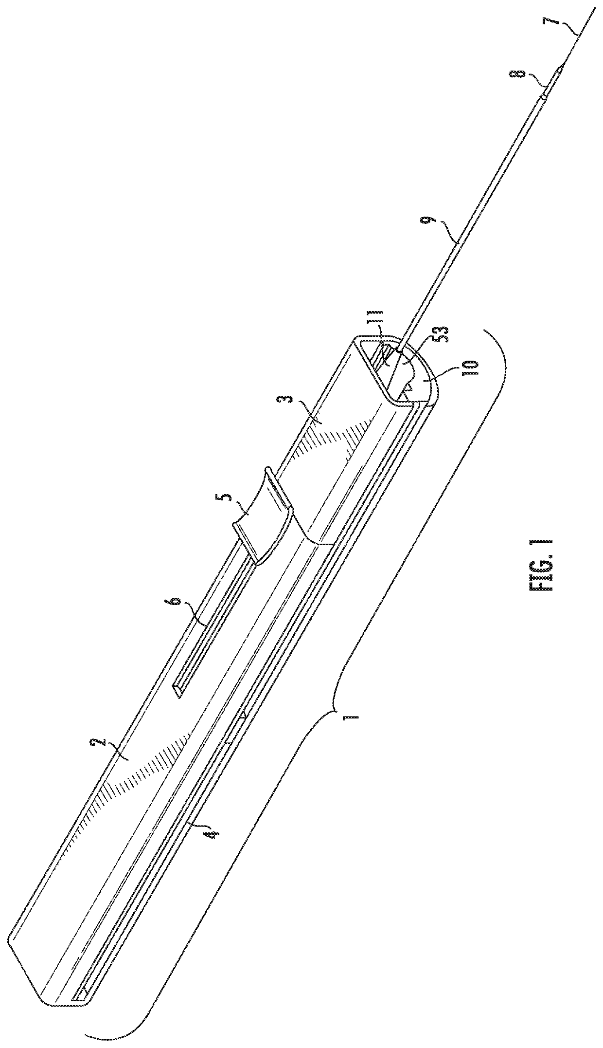
[0043]The present invention will now be described in detail hereinafter by reference to the accompanying drawings. The invention is not intended to be limited to the embodiments described; rather, this detailed description is provided to enable any person skilled in the art to make and practice the invention.

[0044]As used herein, the terms “proximal” and “distal” are used to refer to the axial ends of the safety device, catheter, and various components. The term “proximal end” refers to the end closely adjacent the user of the assembly and the term “distal end” refers to the end of the catheter assembly that is percutaneously inserted into the patient, i.e., adjacent the needle tip. Also, as used herein, the “axial direction” refers to the longitudinal axis of the component or device from the proximal end to the distal end. The term “transverse” direction refers to a direction which intersects the longitudinal axis, at any angle.

[0045]The components of the safety device described he...


PUM


Abstract

The medical safety device utilizes an active needle retraction assembly and a guidewire retraction assembly which retracts the guidewire at a retraction rate greater than the needle retraction rate to safely manage significant lengths of guidewire. A passive retraction system may be used with the active retraction assembly to rapidly retract the needle and guidewire after initial retraction. The guidewire retraction assembly includes a pulley system to increase forces applied to the device to retract the guidewire and needle retraction assembly retracts the needle. The device encloses the needle and guidewire to protect from contact with contaminated materials.

Description

CROSS-REFERENCE TO RELATED APPLICATIONS[0001]The present invention is a continuation of International Application No. PCT / US2018 / 032474, filed May 18, 2018, which claims the benefit of priority to U.S. Provisional Application No. 62 / 505,902, filed May 13, 2017, and to U.S. Provisional Application No. 62 / 567,470, filed Oct. 3, 2017, each of which is incorporated by reference in their entirety.FIELD OF THE INVENTION[0002]The present invention is directed, generally, to safety devices used in connection with medical devices for providing intravascular access into a blood vessel, including veins, arteries, or other anatomical structure. More specifically, the safety device allows for simultaneous retraction of both a needle and guidewire, both of which are likely contaminated after a medical procedure. The invention allows for both active and passive retraction into a protective housing to minimize the risk of injury or infection to the user.BACKGROUND OF THE INVENTION[0003]Catheters ar...

Claims


Application Information

Patent Timeline
IPC IPC(8): A61M25/06A61M25/09
CPCA61M25/0606A61M25/09041A61M25/0631A61M5/32
Inventor MITCHELL, JAMES D.THORESON, ANDREW A.
Owner REDSMITH INC
Why Eureka
Try Eureka