
Robot calibration for ar and digital twin

a robot and digital twin technology, applied in the field of industrial robots, can solve the problems of large error at longer distances, large effort and high cost associated with placing a planar visual target, and difficult time-consuming calibration of ar devices to achieve the required level of precision

Active Publication Date: 2020-03-12
FANUC ROBOTICS NORTH AMERICA
View PDF0 Cites 13 Cited by
  • Summary
  • Abstract
  • Description
  • Claims
  • Application Information

AI Technical Summary

Benefits of technology

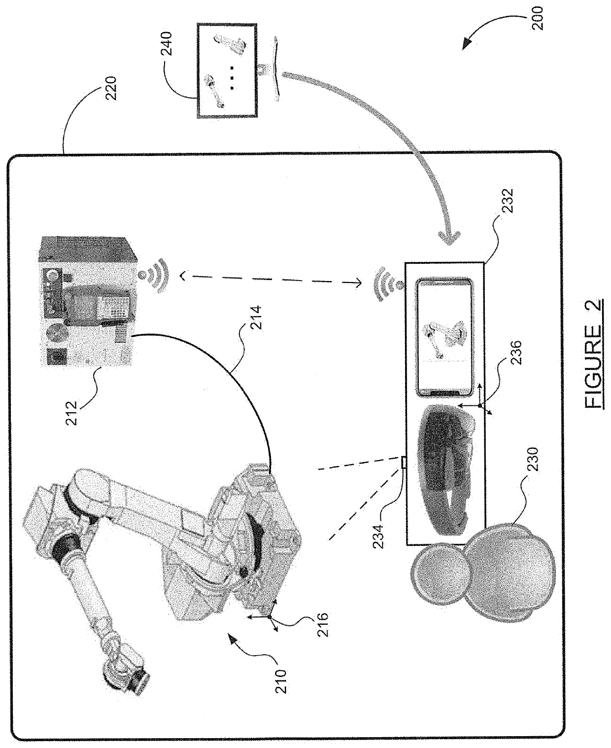
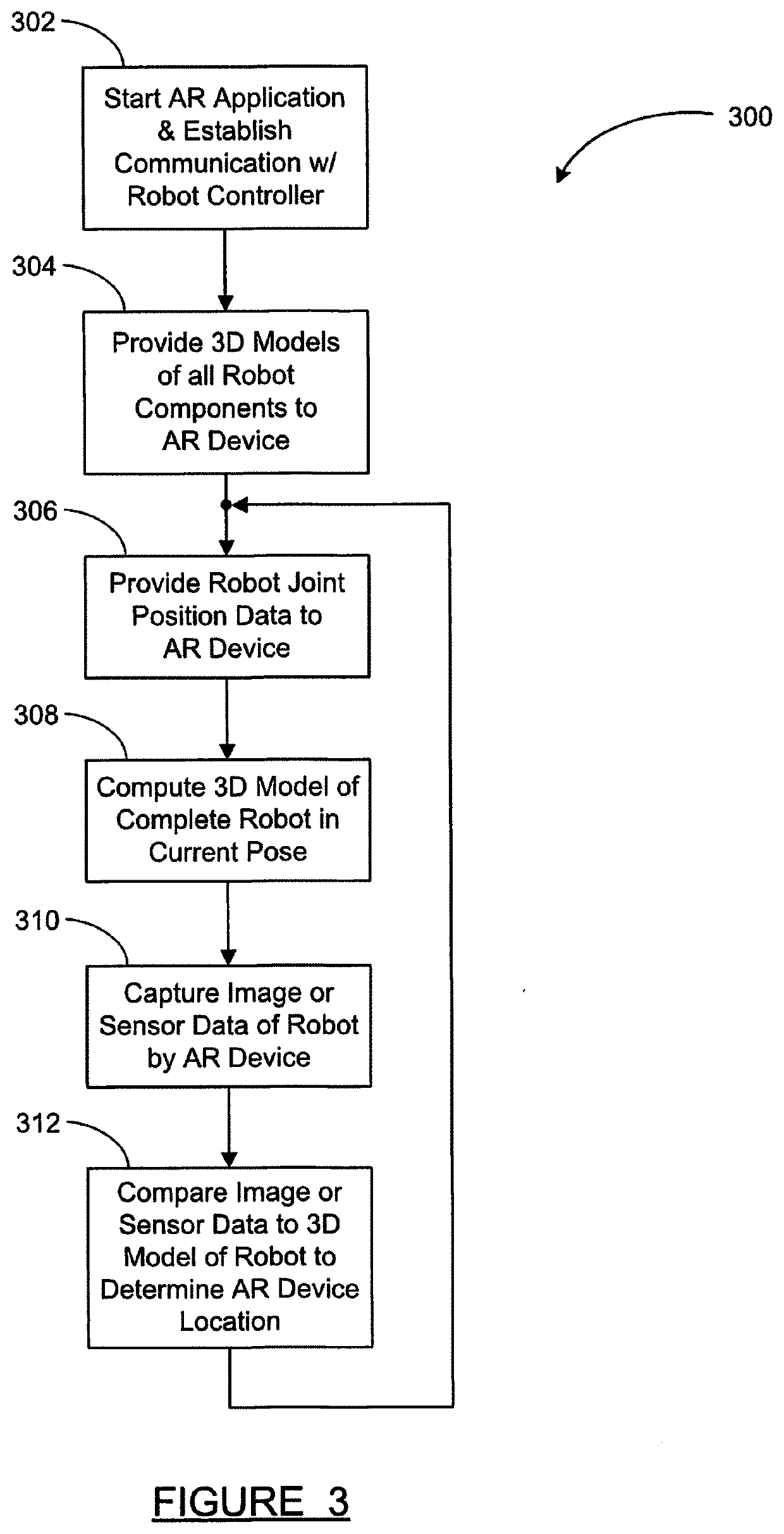
The present patent describes a method for calibrating an augmented reality device using a robot's position. Rather than using a visual calibration target, the robot's position is used as a reference frame. The robot's surface model is combined with individual arm models to create a 3D model of the robot in its current pose. This 3D model is then used to calibrate the augmented reality device by analyzing images from its camera. This method can be used for both initial calibration and ongoing device tracking. The technique does not require a separate visual calibration target.

Problems solved by technology

Unfortunately, calibration of AR devices to achieve the required level of precision has traditionally been difficult and time consuming.
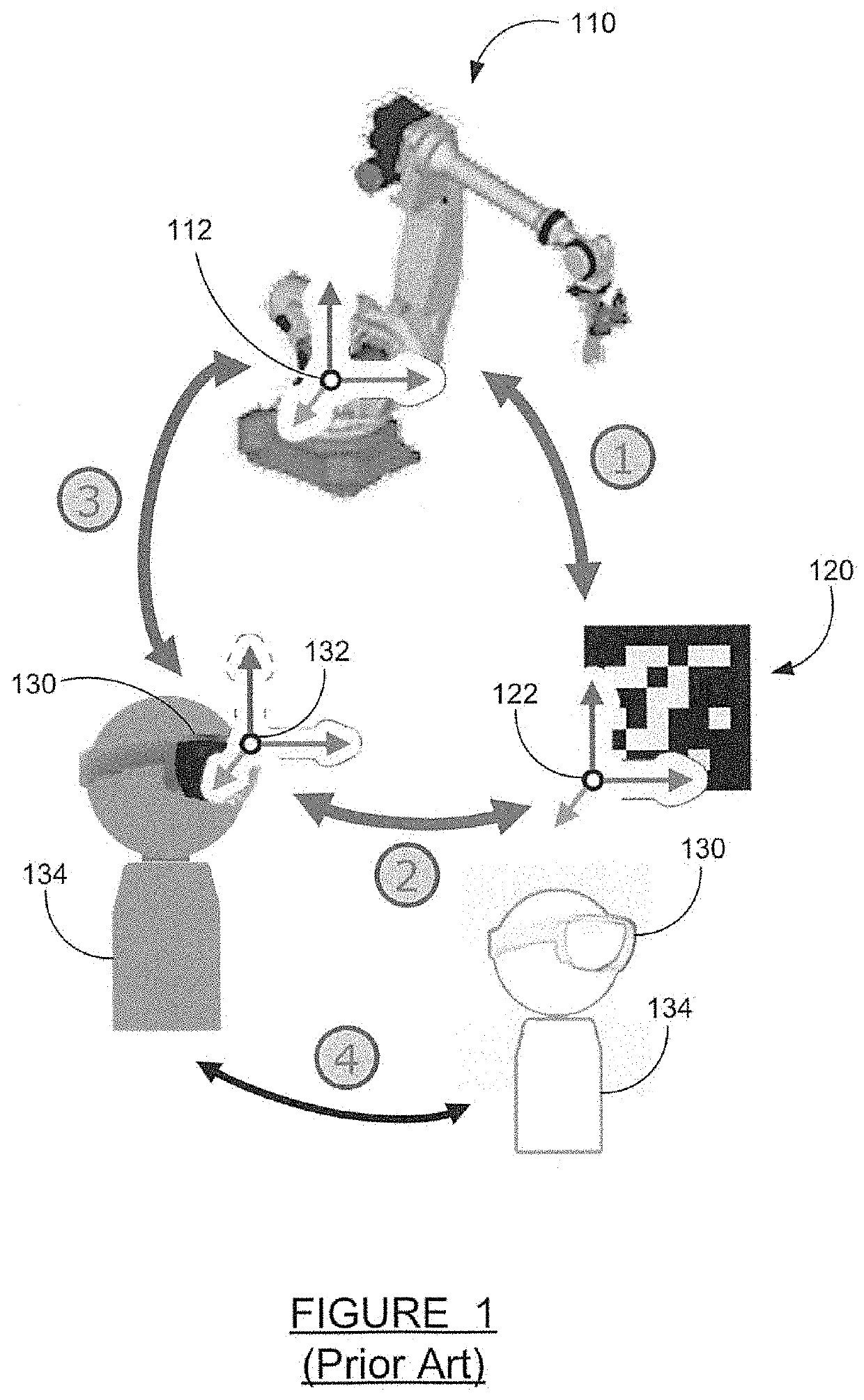
However, there is a large effort and a high cost associated with placing a planar visual target or “fiducial” (fixed basis of comparison) at some precise fixed location in the robot work cell.
Any small tilt in the calibration plane could lead to large errors at longer distances.
Any indirect calibration will result in calibration imprecision.
Imprecise calibration leads to inaccuracies and limitations in AR system functionality.
Furthermore, calibrating to a 3D model of the robot in a single predefined pose may not be very precise because information is localized, and some robot axes may be occluded.
Also, there is not much high frequency information in a robot axis, so information from a single robot axis may result in calibration imprecision.
Also, “delta”-type robots (pick-and-place robots with multiple parallel links) could be impossible to calibrate using single axis methods.

Method used


Image

  • Robot calibration for ar and digital twin
  • Robot calibration for ar and digital twin
  • Robot calibration for ar and digital twin

Examples


Embodiment Construction

[0012]The following discussion of the embodiments of the disclosure directed to a calibration of an augmented reality (AR) device's position and orientation based on a 3D surface model of a robot in any pose is merely exemplary in nature, and is in no way intended to limit the disclosed devices and techniques or their applications or uses.

[0013]The use of augmented reality (AR) systems in conjunction with industrial robots is known. For example, an AR system which assists a human operator in defining operational bounding zones was described in U.S. patent application Ser. No. 16 / 453,811, titled “VISUALIZATION AND MODIFICATION OF OPERATIONAL BOUNDING ZONES USING AUGMENTED REALITY”, filed Jun. 26, 2019, hereby incorporated by reference in its entirety. In addition, an AR system which assists an operator in defining robot pick-and-place parameters was described in U.S. patent application Ser. No. 16 / 453,838, titled “AUGMENTED REALITY VISUALIZATION FOR ROBOTIC PICKING SYSTEM”, filed Jun...


PUM


Abstract

A method and system for calibration of an augmented reality (AR) device's position and orientation based on a robot's positional configuration. A conventional visual calibration target is not required for AR device calibration. Instead, the robot itself, in any pose, is used as a three dimensional (3D) calibration target. The AR system is provided with a CAD model of the entire robot to use as a reference frame, and 3D models of the individual robot arms are combined into a single object model based on joint positions known from the robot controller. The 3D surface model of the entire robot in the current pose is then used for visual calibration of the AR system by analyzing images from the AR device camera in comparison to the surface model of the robot in the current pose. The technique is applicable to initial AR device calibration and to ongoing device tracking.

Description

CROSS-REFERENCE TO RELATED APPLICATIONS[0001]This application claims the benefit of the priority date of U.S. Provisional Patent Application Ser. No. 62 / 729,174, titled ROBOT CALIBRATION FOR AR AND DIGITAL TWIN, filed Sep. 10, 2018.BACKGROUNDField[0002]The present disclosure relates to the field of industrial robots and, more particularly, to a method for calibration of an augmented reality (AR) device's position and orientation based on a robot's positional configuration, where a conventional visual calibration target is not required, the AR system is provided with a static CAD model of the entire robot in a current pose as a reference frame, and 3D models of the individual robot arms are combined into a single object model for visual calibration of the AR system.Discussion of the Related Art[0003]The use of augmented reality (AR) systems in conjunction with industrial robots is known in the art. An AR system can be used, for example, in teaching a robot how to perform a certain op...

Claims


Application Information

Patent Timeline
IPC IPC(8): B25J9/16B25J13/08G06T7/73
CPCG06T7/75B25J13/089B25J9/1697B25J9/1605B25J9/1692G05B2219/39451G05B2219/39059G05B2219/39014G06F3/011G06F3/0346G06F3/017G06T2207/30244
Inventor KRAUSE, KENNETH W.JUNG, DEREKKESELMAN, LEO
Owner FANUC ROBOTICS NORTH AMERICA
Learn More