
Connector structure

a technology of connecting structure and connecting rod, which is applied in the direction of multiple conductor connectors, coupling contact members, coupling device connections, etc., can solve the problems of increasing labor costs, increasing the commonality (use range) of both products and semi-products, and causing waste of more waste materials. , to achieve the effect of enhancing the economic profit of the product, reducing waste materials, and reducing the size of stretched materials

Active Publication Date: 2020-03-19
SWITCHLAB +2
View PDF12 Cites 1 Cited by
  • Summary
  • Abstract
  • Description
  • Claims
  • Application Information

AI Technical Summary

Benefits of technology

The present invention is a connector structure that includes a case seat assembly and multiple plug assemblies in a predetermined form. The plug assemblies have a conductive section and a wire connection member connected by a flexible connection section. A pressing leaf spring is disposed in each wire connection member, with an abutment end and a lateral protrusion section. An unlocking assembly is also included with a push member and an elastic member. The connector structure has the benefits of minimizing the size of the components and reducing waste material, and can be used for various connector products with different specifications. Additionally, the connector structure includes multiple lateral sink sections and lateral protrusion sections that securely connect the case seats with each other.

Problems solved by technology

In the field of connectors mated and connected with each other, it is a critical issue how to easily assemble and connect the connector with the conductive wire and keep the conductive wire securely connected with the connector without loosening after assembled.
As a result, more waste material will be produced to cause waste.
In addition, the commonness (use range) of both the product and semi-product is limited.
In the case that the connection member is welded between the conductor connection holder and the plug, the labor cost will be inevitably increased.
This directly leads to increase of cost.
Therefore, there are still the problem that the labor cost and manufacturing cost are increased.
This leads to inconvenience in operation and use.
Also, due to the limitation of the material and size, the connection strength between the rotary lever and the case is poor.
Therefore, due to wear or improper use, the rotary lever is apt to loosen or damage.
As a result, the rotary lever can hardly effectively push the contact leaf spring.

Method used


Image

  • Connector structure
  • Connector structure
  • Connector structure

Examples


Embodiment Construction

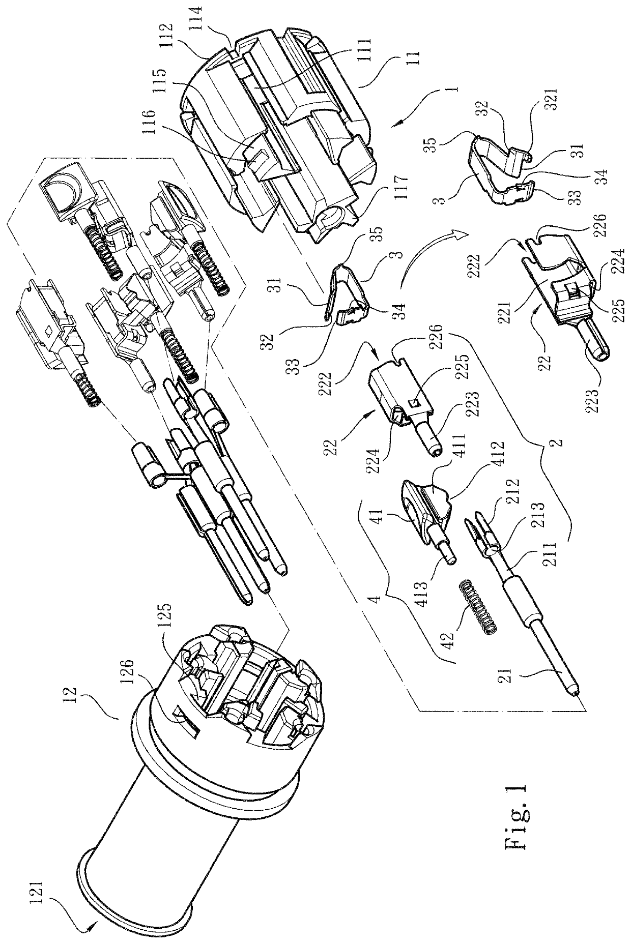
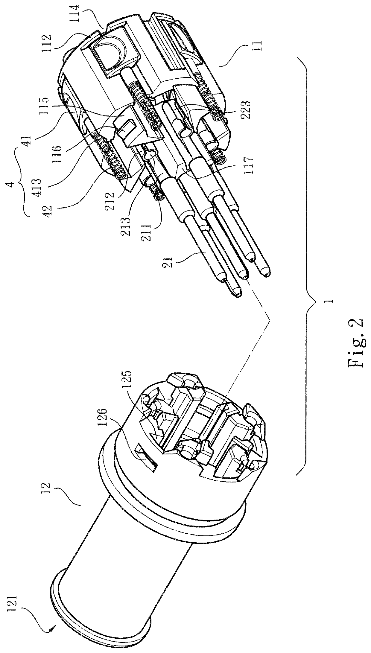
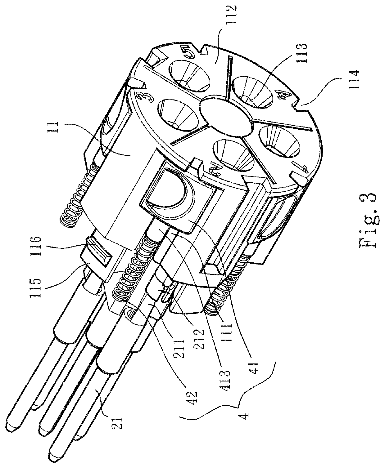
[0034]Please refer to FIGS. 1 to 7. The connector structure of the present invention includes a case seat assembly 1, a plug assembly 2, a pressing leaf spring 3 and an unlocking assembly 4. The case seat assembly 1 includes a first case seat 11 and a second case seat 12 connected with each other. Multiple inward recessed channels 111 are formed on outer circumference of the first case seat 11 and axially extend. Multiple lateral protrusion sections 115 are disposed at one end of the first case seat 11 in adjacency to the second case seat 12.

[0035]In a preferred embodiment, multiple stop sections 112 are disposed at one end of the first case seat 11 distal from the second case seat 12 and extend into the channels 111 respectively. Each of the stop sections 112 is formed with a wire socket 113 and a notch 114 corresponding to the channel 111.

[0036]A cavity 121 and an end recess 127 are respectively formed on two opposite end faces of the second case seat 12. Multiple passages 122 are...


PUM


Abstract

A connector structure includes a case seat assembly and plug assemblies. Two ends of the case seat assembly are formed with channels. Each plug assembly has a conductive section and a wire connection member. The wire connection member is formed with a receiving space for receiving a pressing leaf spring. Each pressing leaf spring has an abutment end. A lateral protrusion section is disposed on the abutment end. Multiple unlocking assemblies are disposed beside the wire connection member. Each unlocking assembly has a push member formed with a push block. The lateral protrusion section is positioned in a sliding path of the push block along the channel, whereby the lateral protrusion section can be pushed to drive the abutment end to release a conductive wire.

Description

BACKGROUND OF THE INVENTION1. Field of the Invention[0001]The present invention relates generally to a connector structure, and more particularly to a connector structure, which can reduce material consumption and diversify the use.2. Description of the Related Art[0002]In the field of connectors mated and connected with each other, it is a critical issue how to easily assemble and connect the connector with the conductive wire and keep the conductive wire securely connected with the connector without loosening after assembled.[0003]For example, a prior art discloses a plug-type connector including a contact carrier component. Multiple contacts are disposed in the contact carrier component corresponding to hollow cylindrical cases arranged in different positions. Each contact includes a conductor connect ion holder, a plug and a flexible connect ion member connected between the conductor connection holder and the plug. A stranded wire can be inserted into the conductor connection ho...

Claims


Application Information

Patent Timeline
Patent Type & Authority Applications(United States)
IPC IPC(8): H01R4/48H01R13/502
CPCH01R4/4836H01R13/502H01R4/4827H01R13/5804H01R13/02H01R4/4833H01R4/4821H01R4/4846H01R13/506H01R11/05H01R13/4367H01R4/48365H01R4/48275H01R4/48185
Inventor WU, CHIH-YUANHSIAO, CHIH-KUN
Owner SWITCHLAB
Learn More