Counter top cooking appliance

a technology for cooking appliances and counter tops, applied in the direction of domestic stoves or ranges, heating types, lighting and heating apparatuses, etc., can solve the problems of product not being useful, putting away, and putting away, and achieve the effect of optimal performan

Active Publication Date: 2020-03-26
GLUCKSMAN DOV Z
View PDF0 Cites 27 Cited by
  • Summary
  • Abstract
  • Description
  • Claims
  • Application Information

AI Technical Summary

Benefits of technology

[0010]The food holder may be a cylindrical food basket having two horizontal axles extending coaxially, and oppositely outwardly there-from. Each of the two horizontal axles may be releasably supportable by the food holder support, so that the two horizontal axles are coaxial with the horizontal axis when the cylindrical food basket is there-at, and rotation of the food holder within the cooking compartment may be rotation of the cylindrical food basket about the two horizontal axles for uniform exposure of the food therein to the at least one source ofheat.
[0015]The food tray may be further adapted to engage the guide such that the at least a portion of the food tray maintains a horizontal disposition in the first tray location, at the vertical axis, and during shuttling there-between. The guide may be a pair of guide channels, each disposed on an opposite sidewall of the cooking compartment, and wherein the food tray may be a planar food tray having a first pair of horizontal tray pins extending coaxially and oppositely outwardly there-from. Each of the first pair of horizontal tray pins may be releasably supportable by the food holder support. The food tray may also have a second pair of horizontal tray pins extending oppositely outwardly there-from, each of the second pair of horizontal tray pins releasably engaging one of the guide channels when the food tray is at the first tray location, at the vertical axis, or anywhere there-between. The cylindrical food basket may include two horizontal basket axles extending coaxially and oppositely outwardly there-from. Each of the two horizontal basket axles may be releasably supportable by the food holder support, so that the two horizontal basket axles are coaxial with the horizontal axis when the cylindrical food basket is there-at, and rotation of the cylindrical food basket may be rotation about the two horizontal basket axles for uniform exposure of the food therein to the at least one source of heat.
[0024]It is an object of this invention to provide a countertop cooking appliance that can optimally perform a variety of cooking modes. It is a further object of this invention to provide a countertop cooking appliance that includes a source of radiant heat as needed in certain cooking modes. It is a further object of this invention to provide a countertop cooking appliance that includes source of convective heat as needed in certain cooking modes. It is a further object of this invention to provide a countertop cooking appliance that includes programmable controller capable of controlling both heating sources in a manner that would be best suitable for certain cooking modes.
[0025]It is a further object of this invention to provide a countertop cooking appliance that includes a hinged door for access to the cooking compartment of the appliance. It is a further object of this invention to provide a drive means integral of the cooking appliance for rotating the food stuff to expose the food stuff uniformly to the sources of heat. It is a further object of this invention to provide a cylindrical basket including two axles extending outwardly from the cylindrical basket. Each of the two axles are releaseably supported by two arms integral to the hinged door, so that when the hinged door is closed the cylindrical basket engages the drive means causing the container to rotate about its horizontal axis for exposing different parts of the food stuff to the radiant source of heat. When the hinged door is opened the cylindrical basket is disengaged from the drive means and is removed from the interior of the cooking appliance for ease or removal by the operator.
[0027]It is a further object of this invention to provide a horizontal platform to support food stuff being cooked. The horizontal platform is supported on a frame so it is free to spin about its vertical axis. The frame includes two sets of outwardly extending pins. One set of pins is designed to slide in a set of tracks integral to the left and right wall of the cooking compartment. Second set of pins are releaseably supported by two arms integral to the hinged door, so that when the hinged door is closed the horizontal platform engages the drive means causing the platform to rotate about its vertical axis for exposing different parts of the food stuff to the sources of heat. When the hinged door is opened the horizontal platform is disengaged from the drive means and is removed from the interior of the cooking appliance for ease of removal by the operator.

Problems solved by technology

While serving well as a product for roasting chicken and other fowl to perfection the product would not be useful otherwise and would have to be put away once the chicken is cooked, as it takes a lot of space on the countertop.
While serving well for air frying and other similar dishes the product would not be useful otherwise and would have to be put away once the French Fries are cooked, as it takes a lot of space on the countertop.
There are many other appliances available on the market that are effective in cooking one specific type of food or another, but at the end of the cooking session that product would have to be put away as it takes a lot of space on the countertop.

Method used


Image

  • Counter top cooking appliance
  • Counter top cooking appliance
  • Counter top cooking appliance

Examples


Embodiment Construction

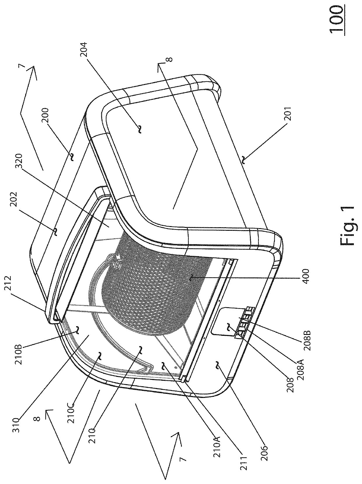
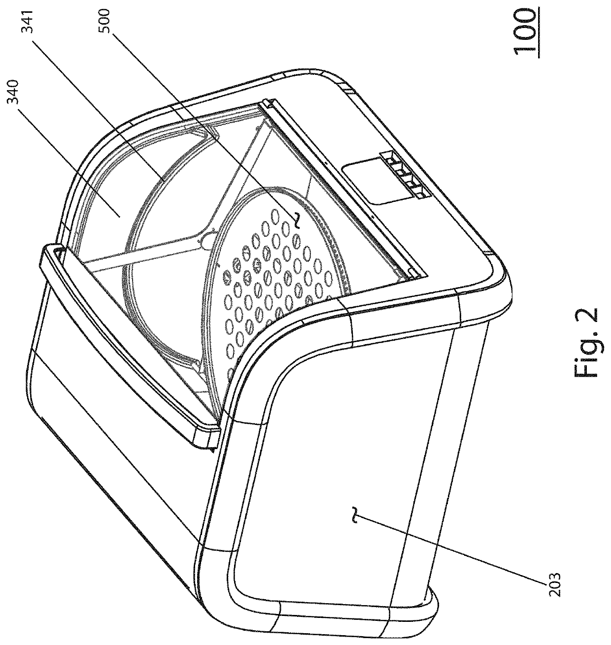
[0057]A first exemplary countertop cooking appliance 100 in accordance with and / or for use in practicing to the invention is shown as isometric views in FIG. 1 and FIG. 2. In particular, an outer enclosure 200 consists of a bottom 201 a top 202 a left side 203 a right side 204, a rear 205 (not shown) and a front 206. Also shown a hinged door 210, preferably partially or fully transparent, with a hinge 211 at its lower end and a handle 212 at its upper end. The hinged door 210 which may be made of glass or high temperature plastics consists of two plane portions 210A and 210B and a curved portion 210C connecting the two. Also shown is a user interface 208 consisting of a series of buttons 208A and a display 208B.

[0058]Also visible through transparent door 210 in FIG. 1 and FIG. 2 are side walls 310, 340 and 320 ofthe cooking compartment 300 as well as cylindrical basket 400 and horizontal platform for supporting food stuff 500.

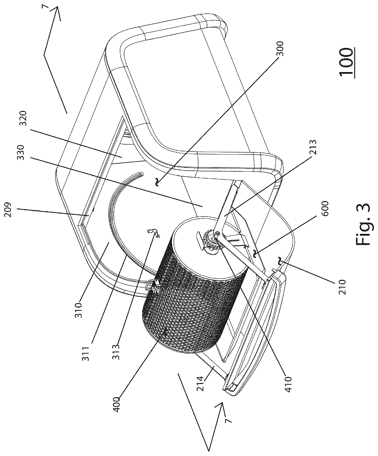
[0059]FIG. 3 is an isometric view of the countertop cooki...


PUM


Abstract

A countertop electric appliance optimally performs a variety of cooking modes with both radiant and convective heat sources as well as control means for controlling the timing and intensity of the heat sources. A driver turns food about either a horizontal or a vertical axis of rotation suitable for the specific food and recipe. A hinged door supports the food to be cooked so that in one location the food is caused to be turned by the drive means and in another location the food is loaded into or removed from the appliance, external of the cooking compartment, to be easily handled by the operator.

Description

RELATED APPLICATION[0001]This application is a Continuation-in-Part of U.S. Ser. No. 15 / 078,933 filed on 23 Mar. 2016, which was a non-Provisional Continuation of U.S. Provisional Application No. 62 / 136,853 filed on 23 Mar. 2015, the teachings of which are incorporated herein in their entireties by reference.FIELD OF THE INVENTION[0002]This invention generally relates to an electric appliance for cooking and baking food stuff. More specifically this invention relates to a method and apparatus for cooking and baking a variety of food items and following a variety of recipes, by using a combination of radiant heat transfer to the food and convective heat transfer to the food in a sequence and manner that is best suitable for achieving optimal cooking results for each type of food and recipe.BACKGROUND[0003]Over the past few decades healthy cooking has become more popular as a result of the medical profession having identified the ties between serious ailments such as heart failure, di...

Claims


Application Information

Patent Timeline
Patent Type & Authority Applications(United States)
IPC IPC(8): A47J37/04F24C15/16
CPCF24C15/164A47J37/041A47J37/046A47J37/047A47J37/0641F24C15/162F24C15/325
Inventor GLUCKSMAN, DOV Z.
Owner GLUCKSMAN DOV Z
Why Eureka
Try Eureka