
Instrument for attaching to a bone anchor and instrument for use in distraction and/or retraction, in particular for orthopedic surgery or neurosurgery, more specifically for spinal surgery

a bone anchor and instrument technology, applied in the field of instruments for attaching to bone anchors, can solve the problems of difficult attachment or holding of instruments, limited surgical site visibility, retraction, etc., and achieve the effect of reducing the available space for surgical manipulation

Active Publication Date: 2020-03-26
BIEDERMANN TECH GMBH & CO KG
View PDF0 Cites 3 Cited by
  • Summary
  • Abstract
  • Description
  • Claims
  • Application Information

AI Technical Summary

Benefits of technology

The patent describes a retractor blade that can be attached to a bone anchoring element in spinal surgery. The retractor blade is designed to be easily attached and secure, even in minimally invasive surgeries or surgeries with poor visibility. The attachment is assisted by a spring force, which prevents unwanted detachment. The retractor blade can be mounted to the instrument's arms at a predefined angle, allowing for easy retraction of soft tissue and improved visibility. The retractor blade is also pivotable in a single plane relative to the instrument's arm to adapt to varying geometrical situations at the surgical site. Overall, the patent provides a simple and reliable solution for spinal surgery procedures.

Problems solved by technology

In MIS, visibility of the surgical site is very limited.
Moreover, known techniques for distraction and / or retraction in some cases may involve difficulties in attaching or holding the instruments while performing distraction and / or retraction steps.

Method used


Image

  • Instrument for attaching to a bone anchor and instrument for use in distraction and/or retraction, in particular for orthopedic surgery or neurosurgery, more specifically for spinal surgery
  • Instrument for attaching to a bone anchor and instrument for use in distraction and/or retraction, in particular for orthopedic surgery or neurosurgery, more specifically for spinal surgery
  • Instrument for attaching to a bone anchor and instrument for use in distraction and/or retraction, in particular for orthopedic surgery or neurosurgery, more specifically for spinal surgery

Examples


Embodiment Construction

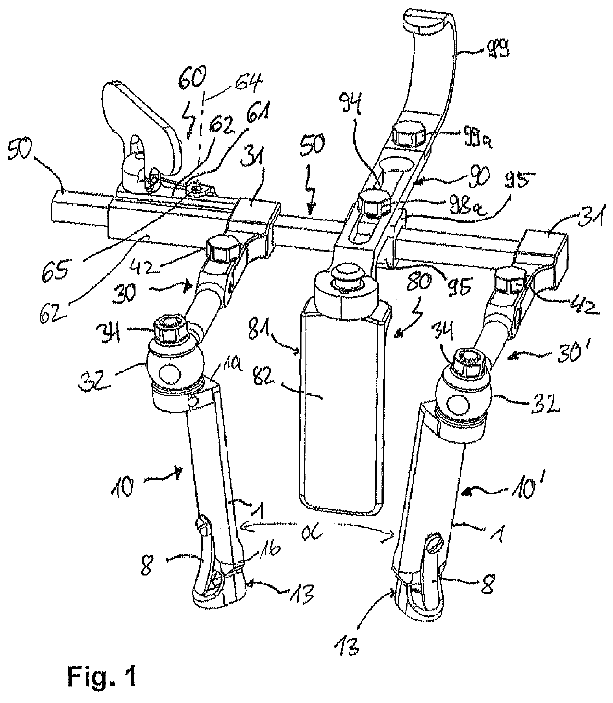
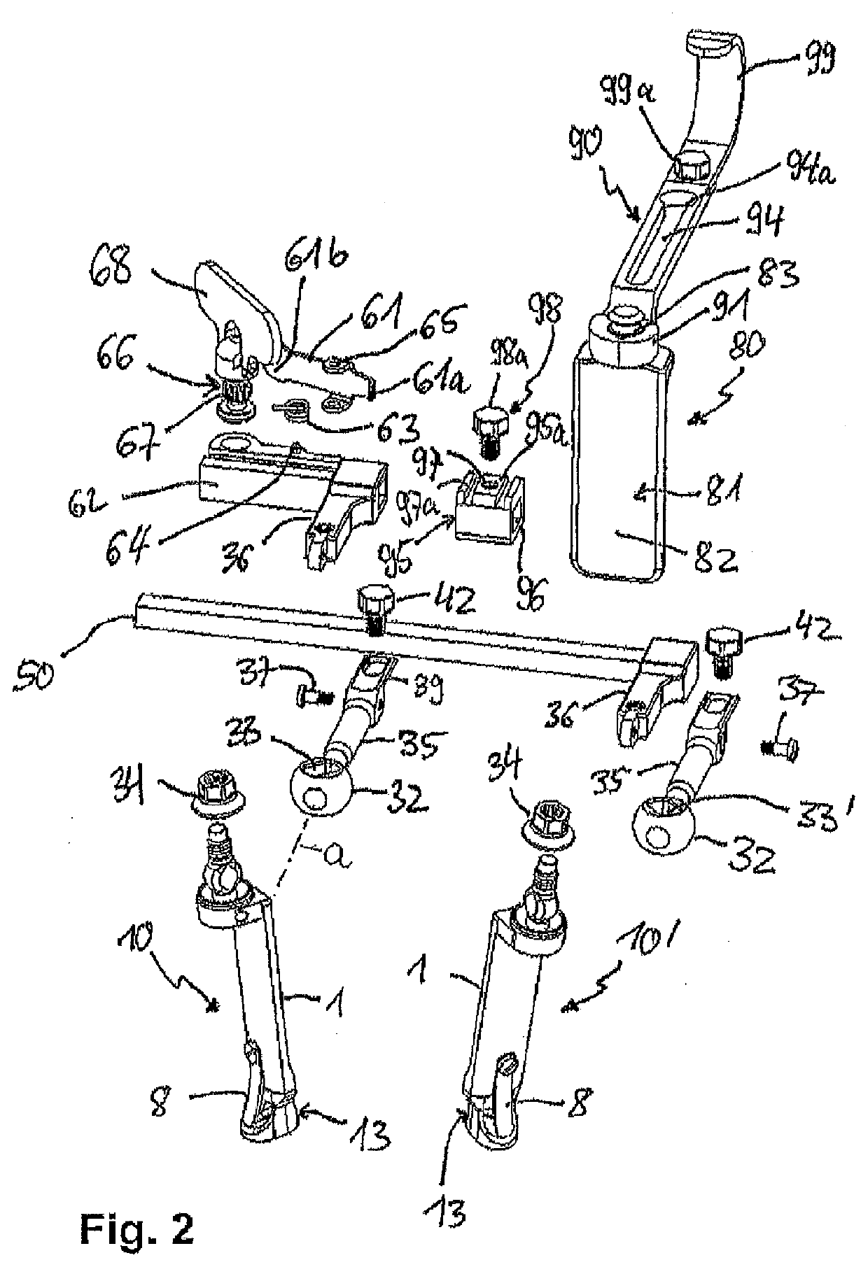
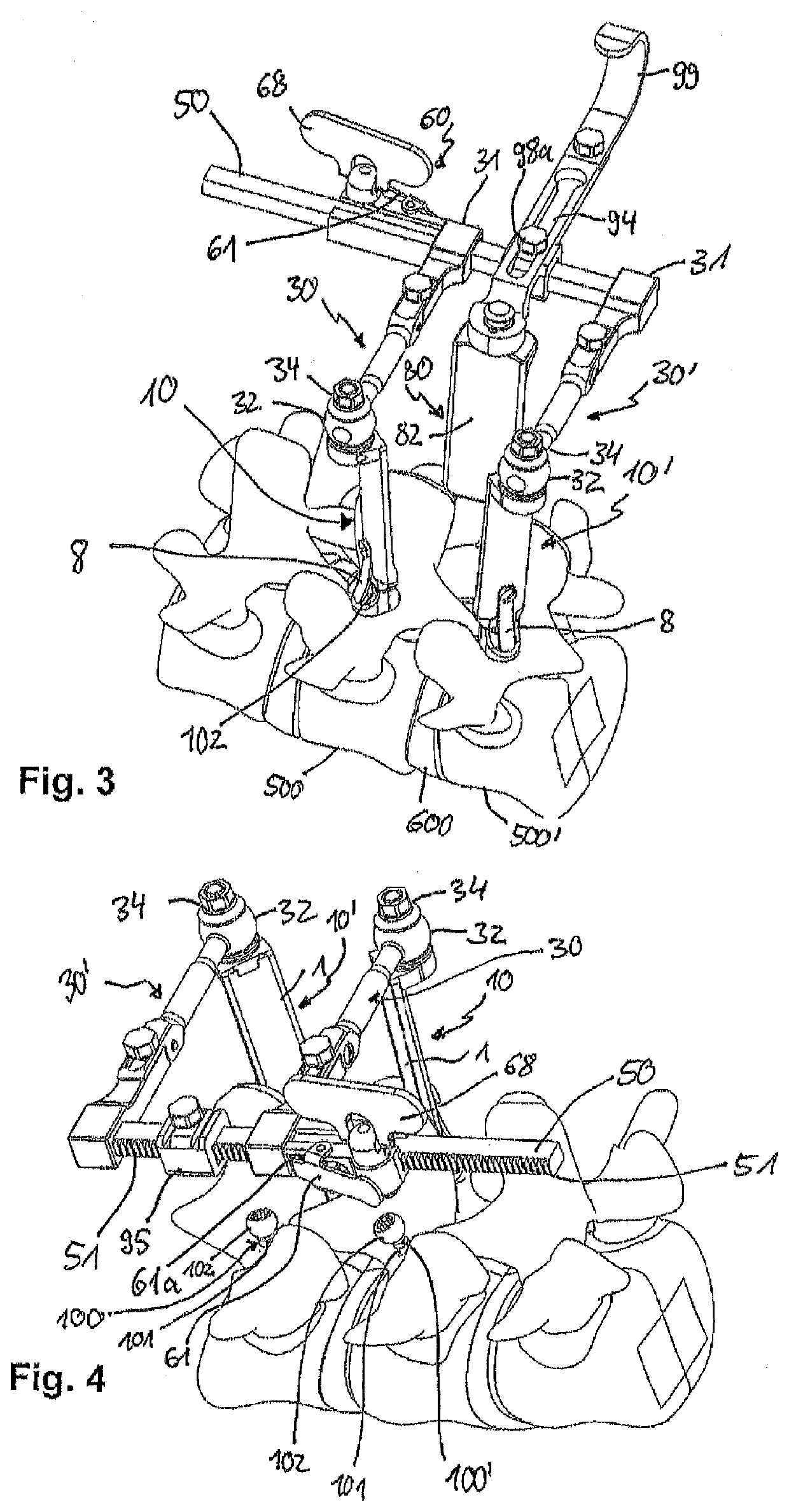
[0052]Referring to FIGS. 1 to 4, an instrument according to an embodiment of the invention includes a first retractor blade 10 and a second retractor blade 10′ that are configured to be connected to bone anchoring elements, for example, bone anchoring elements 100, 100′ as shown in FIGS. 3 and 4. The retractor blades 10, 10′ shown with the instrument each forms an embodiment of an instrument itself for attaching to a bone anchor, according to aspects of the invention.

[0053]Each bone anchoring element 100, 100′ includes a shank 101 that is configured to be anchored in bone, for example in the pedicle of a vertebra, and which may be threaded, and a head 102 that has preferably a spherically-shaped outer surface portion. The first retractor blade 10 and the second retractor blade 10′ are connectable to a first arm 30 and a second arm 30′, respectively, which are attached to a frame that may be a positioning rod 50, that permits positioning of the first and second arms 30, 30′ relative ...


PUM


Abstract

An instrument configured to attach to a bone anchoring element during surgery includes an elongate portion and an end portion having a first side and an opposite second side, where the elongate portion extends away from the first side, and where an opening is defined at the second side to accommodate at least a portion of a head of the bone anchoring element. The opening of the end portion has a first section sized to permit insertion and removal of the head therethrough, and a second section forming a seat for the head. When the head is held in the seat, the seat prevents removal of the head through the opening, while the head is movable unobstructedly from the second section back towards the first section.

Description

CROSS-REFERENCE TO RELATED APPLICATION(S)[0001]The present application claims priority to and the benefit of U.S. Provisional Patent Application No. 62 / 734,485, filed Sep. 21, 2018, the contents of which are hereby incorporated by reference in their entirety, and claims priority from European Patent Application EP 18 196 118.6, filed Sep. 21, 2018, the contents of which are hereby incorporated by reference in their entirety.BACKGROUNDFiled[0002]The application relates to an instrument for attaching to a bone anchor, more specifically to a retractor blade for attaching to a bone anchor, and to an instrument for use in distraction and / or retraction, in particular for orthopedic surgery or neurosurgery, more specifically for spinal surgery.Description of Related Art[0003]Distraction and compression steps during spinal surgery are well-known in the art. For example, in the case of single or multilevel discectomies, cages, pedicle screws and rods are often used for providing stability to...

Claims


Application Information

Patent Timeline
Patent Type & Authority Applications(United States)
IPC IPC(8): A61B17/88A61B17/02
CPCA61B2017/00353A61B17/0218A61B2017/32113A61B17/0206A61B17/8872A61B1/32A61B2017/925A61B17/7077A61B2017/0256
Inventor BIEDERMANN, TIMODANDANOPOULOS, DIMOSTHENIS
Owner BIEDERMANN TECH GMBH & CO KG
Learn More