
A device for earth fault current compensation in power networks

a technology of power network and fault current compensation, which is applied in the direction of emergency protective arrangements, electrical equipment, and circuit arrangements for limiting excess voltage/current, etc., can solve the problems of large consumer groups being disconnected, two aims that are difficult to combine, and the self-quenching effect of cable grids not working at all, etc., to improve safety, fast elimination, and simple manufacturing

Active Publication Date: 2020-03-26
WINTER BROTHERS AB
View PDF0 Cites 9 Cited by
  • Summary
  • Abstract
  • Description
  • Claims
  • Application Information

AI Technical Summary

Benefits of technology

The patent describes a new device that improves safety and monitoring in electrical networks by quickly removing faults and preventing damage. It is easy to install and can be used with different types of electrical systems. Additionally, the device can control the voltage to compensate for an earth fault and can detect and prevent insulation issues. Overall, this device helps to improve safety and reliability in electrical networks.

Problems solved by technology

Distribution networks, however, normally have radial structures, and therefore constitute a weak link in the overall power transmission system.
Faults on individual distribution lines may lead to disconnection of large groups of consumers.
At a first glance these two aims look difficult to combine.
On the other hand the self-quenching effect does not work at all in cable grids, due to the short distance between live conductor and the earthed cable shield.

Method used


Image

  • A device for earth fault current compensation in power networks
  • A device for earth fault current compensation in power networks
  • A device for earth fault current compensation in power networks

Examples


Embodiment Construction

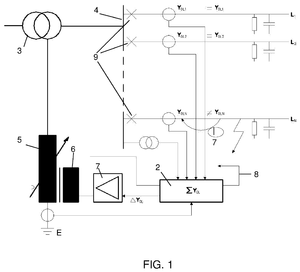
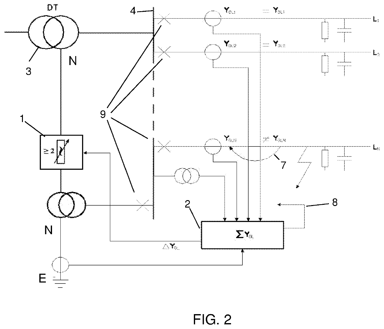
[0041]FIGS. 1 and 2 show a distribution network with a control and measurement unit 2 for the detection of an earth fault and the control of a fault current compensation device. Furthermore the figures show a power transformer 3, a busbar 4 and a number of outgoing feeders L1, L2 . . . LN, each with a line breaker 9 at the busbar 4.

[0042]Electric power transmission is generally effected by means of cyclo symmetrical three phase systems. However, even single and two phase systems (railway) exist. The common ground is that transfer of payload (to the consumers) is driven exclusively by the voltages between the phases. If an error occurs in form of an insulation break down between these phases, the feeder in question and all the consumers behind are disconnected by the line breaker 9.

[0043]However, the majority of electrical faults occur between one of the phases and earth (so called earth faults). Thereby the entire system is shifted in relation to earth. Nevertheless, the voltages be...


PUM


Abstract

A device comprising at least two controllable reactance elements (1) arranged to compensate a single phase-to-earth fault current in a power network with a power transformer (3). The at least two controllable reactance elements (1) are each connected with one side to two different voltages of a three phase voltage source which is synchronous with the power network, and that the reactance elements with their other side are jointly connected to the neutral (N) of the power network or its equivalent. The reactance elements are individually controllable by a control unit (2) designed to control the neutral voltage of the power transformer (3) or its equivalent with respect to amplitude and phase in relation to the power transformer's own voltage system. A method in relation to the device is also disclosed.

Description

FIELD OF THE INVENTION[0001]The invention concerns a device for earth fault current compensation, comprising two or more fast adjustable reactance elements, arranged to compensate for an earth fault current in a power network with a power transformer according to claim 1. Furthermore the invention concerns a method to create a neutral voltage in a power network with a power transformer according to claim 7.BACKGROUND OF THE INVENTION AND PRIOR ART[0002]Today, transfer of electric power is mainly accomplished by means of cyclo-symmetrical three phase voltage systems. To fulfil the basic demands of the system—production and consumption of power must be in balance at all times. In order to facilitate this requirement large national transmission networks have been created, where all producers and consumers of electric power are interconnected. The connection of these national grids to transnational networks provides further advantages with respect to the basic balance requirement. One s...

Claims


Application Information

Patent Timeline
Patent Type & Authority Applications(United States)
IPC IPC(8): H02H9/08
CPCH02H9/08H02J3/26H02J3/1828H02J3/1864
Inventor WINTER, KLAUSWINTER, ANDREASWINTER, HÅKAN
Owner WINTER BROTHERS AB
Learn More