
Occupancy map block-to-patch information compression

a technology of information compression and occupancy map, applied in the field of compression and decompression of point clouds, can solve the problems of cost and time-consuming storage and transmission

Active Publication Date: 2020-04-02
APPLE INC
View PDF0 Cites 30 Cited by
  • Summary
  • Abstract
  • Description
  • Claims
  • Application Information

AI Technical Summary

Benefits of technology

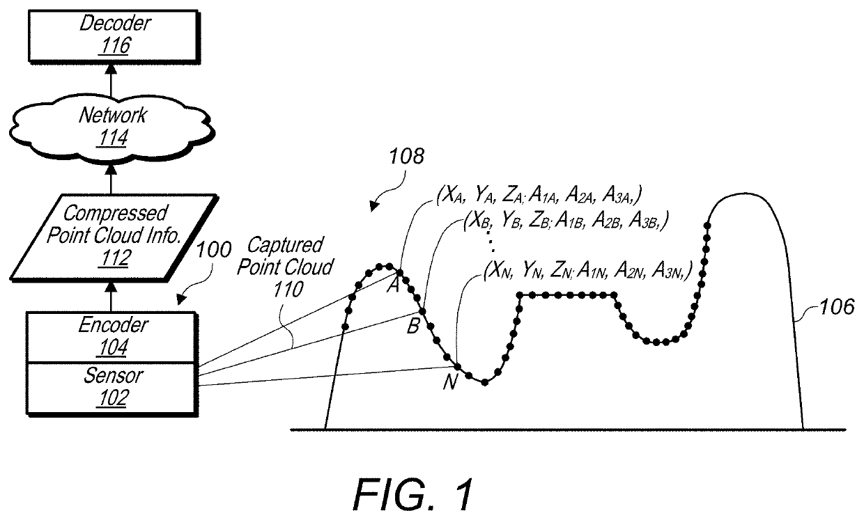
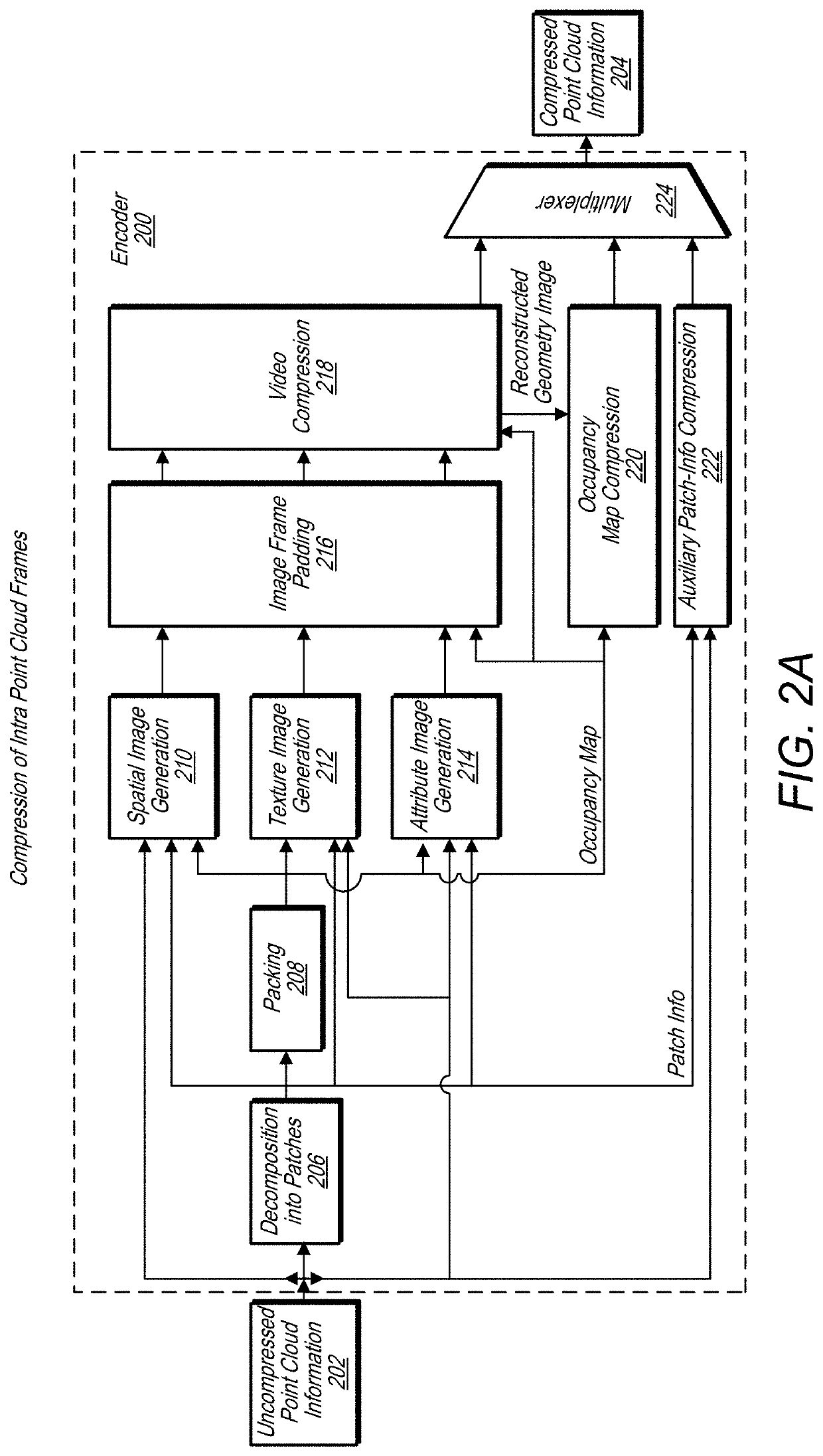
The patent describes a system that includes sensors to capture points that make up a point cloud, which includes information about the location and attributes of each point. The system then compresses this information to save storage space. The system generates patch images for each point in the point cloud, which include the points and geometry information about the points. These patch images can be packed into frames and transmitted over a network for video encoding. The encoded video frames can be decoded and used to reconstruct the original point cloud. The technical effect of this system is to provide a more efficient way to compress and encode point clouds, which can save storage space and reduce bandwidth requirements for transmission.

Problems solved by technology

In either case, such point clouds may include large amounts of data and may be costly and time-consuming to store and transmit.

Method used


Image

  • Occupancy map block-to-patch information compression
  • Occupancy map block-to-patch information compression
  • Occupancy map block-to-patch information compression

Examples


example 3d

Inter-Frame Decoder

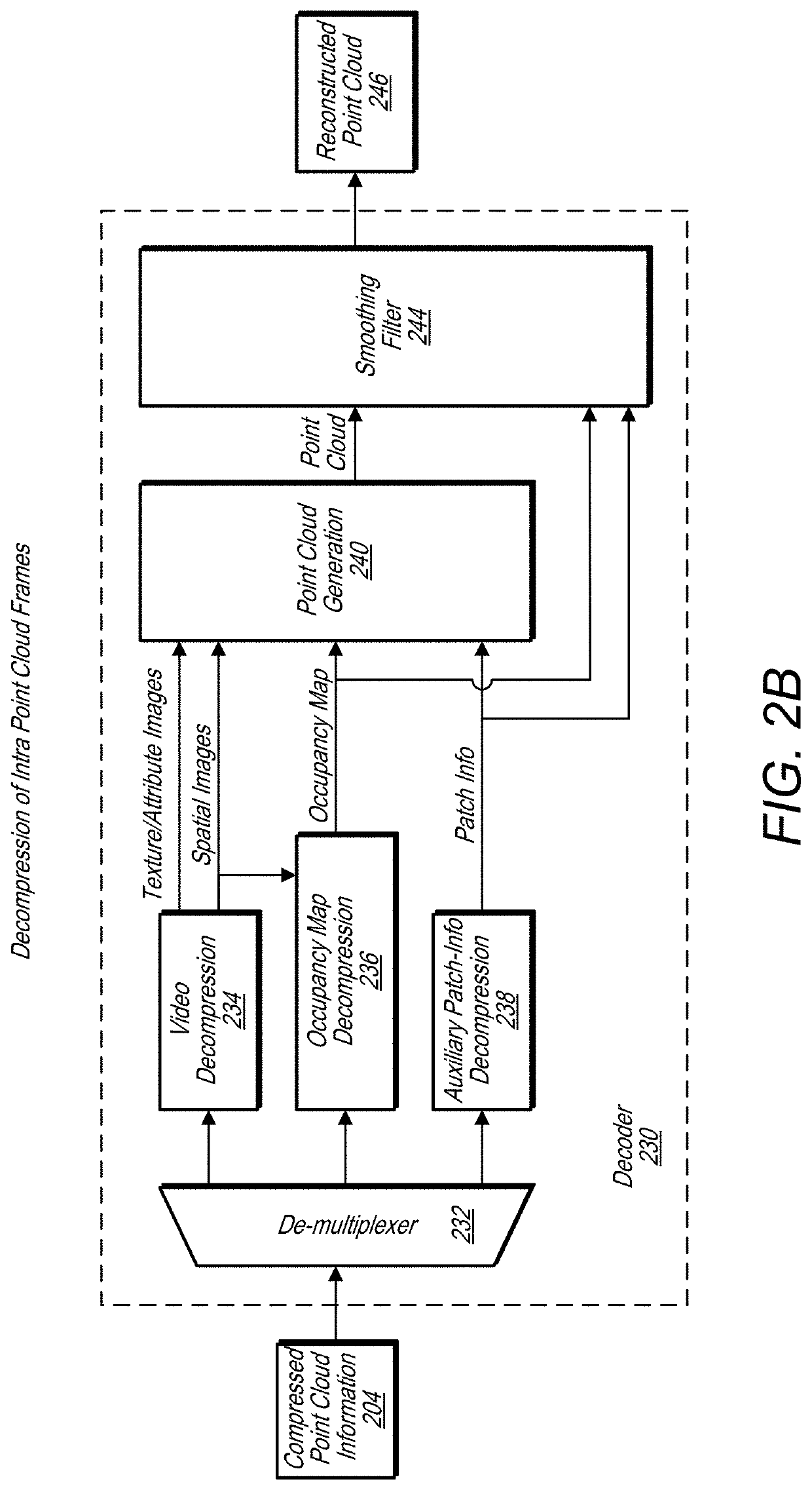
[0089]FIG. 2D illustrates components of a decoder for decoding 3D inter point cloud frames, according to some embodiments. In some embodiments, a decoder, such as decoder 280, includes a video decompression module 270, an inverse 3D motion compensation and inverse delta prediction module 272, a point cloud generation module 274, and a smoothing filter 276. In some embodiments, a decoder, such as decoder 280 may be combined with a decoder, such as decoder 230, or may share some components with the decoder, such as a video decompression module and / or smoothing filter. In decoder 280, the video / image streams are first decoded, then an inverse motion compensation and delta prediction procedure may be applied. The obtained images are then used in order to reconstruct a point cloud, which may be smoothed as described previously to generate a reconstructed point cloud 282.

[0090]While 3D encoding of a point cloud is discussed above in terms of 3D intra-frame compression / d...

example closed form

Solution

[0314]For each point Prec(i) in the reconstructed point cloud, let Q*(i) be its nearest neighbor in the original point cloud. For each point Prec(i) in the reconstructed point cloud, let (Q+(i, h))h∈{1, . . . , H(i))} be the set of point in the original point cloud that share Prec(i) as their nearest neighbor in the reconstructed point cloud. Let +(i) be the centroid of (Q+(i, h))h∈{1, . . . , H(i)}.

If H=0, then C(Prec(i)=C(Q*(i))

[0315]Denote as R-G-B vector C(P) associated with a given point P. In order to compute the color for a given Prec(i) we have the following formulation:

argminC(Prec(i))max{1NrecC(Prec(i))-C(Q*(i))2,1N∑h=1HC(Prec(i))-C(Q+(i,h))2}Wheremax{1NrecC(Prec(i))-C(Q*(i))2,∑h=1HC(Prec(i))-C(ℚ+(i))+C(ℚ+(i))-C(Q+(i,h))2}=max{1NrecC(Prec(i))-C(Q*(i))2,HNC(Prec(i))-C(ℚ+(i))2+1N∑h=1HC(ℚ+(i))-C(Q+(i,h))2+2N∑h=1H〈C(Prec(i))-C(ℚ+(i)),C(ℚ+(i))-C(Q+(i,h))〉}=max{1NrecC(Prec(i))-C(Q*(i))2,HNC(Prec(i))-C(ℚ+(i))2+1N∑h=1HC(ℚ+(i))-C(Q+(i,h))2}

[0316]Now denote D2=Σh=1H∥C(+(i)−C...


PUM


Abstract

A system comprises an encoder configured to compress attribute information and / or spatial information for a point cloud and / or a decoder configured to decompress compressed attribute and / or spatial information for the point cloud. The encoder is configured to convert a point cloud into an image based representation. The encoder packs patch images into an image frame and fills empty spaces in the image frame with a padding. Various compression strategies may be used to encode an occupancy map and related block-to-patch information indicating which portions of the image frame correspond to which packed patches. Packed image frames comprising patches and padding, along with an encoded occupancy map and related block-to-patch information are sent to a decoder. The decoder is configured to generate a decompressed point cloud based on the packed image frames, compressed occupancy map, and related block-to-patch information.

Description

PRIORITY CLAIM[0001]This application claims benefit of priority to U.S. Provisional Application Ser. No. 62 / 740,356, entitled “Occupancy Map Block to Patch Information Compression”, filed Oct. 2, 2018, and which is incorporated herein by reference in its entirety.BACKGROUNDTechnical Field[0002]This disclosure relates generally to compression and decompression of point clouds comprising a plurality of points, each having associated spatial information and attribute information.Description of the Related Art[0003]Various types of sensors, such as light detection and ranging (LIDAR) systems, 3-D-cameras, 3-D scanners, etc. may capture data indicating positions of points in three dimensional space, for example positions in the X, Y, and Z planes. Also, such systems may further capture attribute information in addition to spatial information for the respective points, such as color information (e.g. RGB values), texture information, intensity attributes, reflectivity attributes, motion r...

Claims


Application Information

Patent Timeline
Patent Type & Authority Applications(United States)
IPC IPC(8): G06T9/00
CPCG06T9/001H04N19/597
Inventor MAMMOU, KHALEDTOURAPIS, ALEXANDROSSU, YEPINGKIM, JUNGSUNROBINET, FABRICE AVALENTIN, VALERY G.
Owner APPLE INC
Learn More