Multi-barrel drill guide and anchor deployment assembly

a multi-barrel drill guide and anchor technology, applied in bone drill guides, medical science, surgery, etc., can solve the problems of increased surgical time, increased irritation of the tissue or bone surrounding the pilot hole, and loss of alignment of the drill guide with the pilot hole, so as to minimize irritation/discomfort of patients and damage to the surrounding tissue

Active Publication Date: 2020-04-09
CONMED CORP
View PDF0 Cites 2 Cited by
  • Summary
  • Abstract
  • Description
  • Claims
  • Application Information

AI Technical Summary

Benefits of technology

[0010]The present disclosure is directed to a method for suspension of the CMC joint that minimizes patient irritation / discomfort and damage to the surrounding tissue. According to an aspect, the present invention is a method for suspending a first metacarpal in relative position to a second metacarpal. The method includes the steps of: (i) drilling a hole through the first metacarpal; (ii) inserting a drill guide through the hole in the first metacarpal; (iii) advancing the drill guide to a surface of the second metacarpal, and drilling a hole in the second metacarpal; (iv) inserting an anchor into the hole formed in the second metacarpal, wherein the anchor is attached to suture; (v) deploying the anchor within the second metacarpal; (vi) tensioning the suture attached to the anchor; and (vii) fixing the position of the first metacarpal relative to the second metacarpal using the suture.

Problems solved by technology

Exchanging tools within the drill guide after creation of the pilot hole increases the risk that the alignment of the drill guide with the pilot hole will be lost.
A loss of alignment requires additional surgical time to correct the misalignment, if even possible, and may potentially result in trauma to the tissue or bone surrounding the pilot hole.
Loss of alignment can also result in the anchor inserter rod bending or the anchor not being able to insert fully into the pilot hole which can add cost as well as surgical time.
In addition, traditional suture anchors deployed by conventional drivers are often too large for procedures that involve soft tissue fixation in the extremities.
Ill-fitting suture anchors have increased instability and can cause irritation or damage to tissue surrounding the exposed portion of the anchor.
However, as the size of the traditional suture anchor decreases, the anchor loses retention capacity and thus is unstable within the bone hole.
The number of buttons, especially including the medially positioned button, increases the risk for irritation / discomfort to the patient and damage to the surrounding tissue.
For example, some or all of the discussed patents / publications / products may not be sufficiently early in time, may not reflect subject matter developed early enough in time and / or may not be sufficiently enabling so as to amount to prior art for patent law purposes.

Method used


Image

  • Multi-barrel drill guide and anchor deployment assembly
  • Multi-barrel drill guide and anchor deployment assembly
  • Multi-barrel drill guide and anchor deployment assembly

Examples


Embodiment Construction

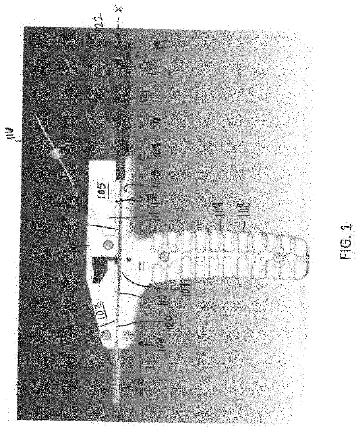
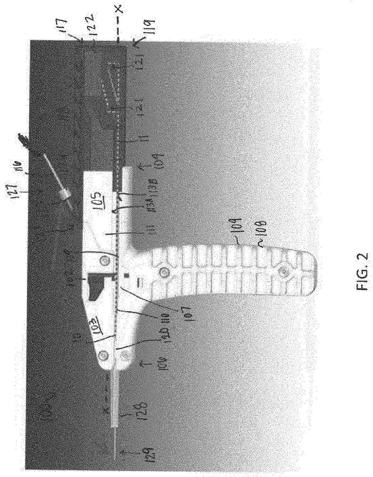
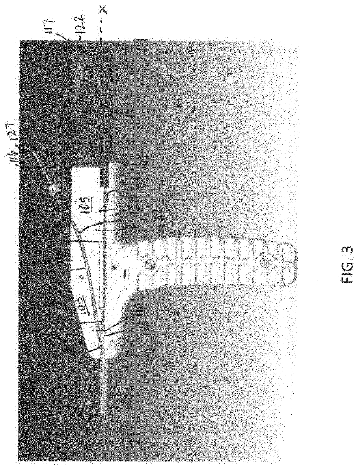
[0089]Referring now to the drawings, wherein like reference numerals refer to like parts throughout, there is seen in FIG. 1 a fully assembled first side 103 view schematic representation of a multi-barrel drill guide and anchor deployment assembly 100 in the pre-drill, pre-anchor deployment, pre-actuated configuration according to an embodiment. In the depicted embodiment, the assembly 100 includes, but is not limited to, a distal elongated body 102 extending along a central longitudinal axis x-x having a proximal end 104 and a distal end 106, a handle 108 (which can include gripping features 109) extending from the elongated body 102 between the proximal end 104 and a distal end 106, a distal tube or guide tip 128 (which can include gripping projections or teeth to assist with setting and maintaining position on bone) extending from the distal end 106, and a proximal sliding inserter / anchor driver 118 / 114. The elongated body 102 has an exterior, portions of which are sufficiently ...


PUM


Abstract

A method for suspension of the CMC joint that minimizes patient irritation / discomfort and damage to the surrounding tissue. Specifically, the method is a method for suspending a first metacarpal in relative position to a second metacarpal. The method includes the steps of: (i) drilling a hole through the first metacarpal; (ii) inserting a drill guide through the hole in the first metacarpal; (iii) advancing the drill guide to a surface of the second metacarpal, and drilling a hole in the second metacarpal; (iv) inserting an anchor into the hole formed in the second metacarpal, wherein the anchor is attached to suture; (v) deploying the anchor within the second metacarpal; (vi) tensioning the suture attached to the anchor; and (vii) fixing the position of the first metacarpal relative to the second metacarpal using the suture.

Description

CROSS-REFERENCE TO RELATED APPLICATION[0001]The present application claims priority to and the benefit of U.S. Provisional Patent Application No. 62 / 742,716, filed on Oct. 8, 2018 and hereby incorporated by reference herein in its entirety. The present application relates to PCT App. No. PCT / US18 / 36011 filed on Jun. 5, 2018, which claims priority to and the benefit of U.S. Provisional Patent Application No. 62 / 515,033, filed on Jun. 5, 2017, U.S. Provisional Patent Application No. 62 / 515,082, filed on Jun. 5, 2017, U.S. Provisional Patent Application No. 62 / 516,733, filed on Jun. 8, 2017, U.S. Provisional Patent Application No. 62 / 618,817, filed on Jan. 18, 2018, and U.S. Provisional Patent Application No. 62 / 649,181, filed on Mar. 28, 2018, each of which is hereby incorporated by reference into this document in their respective entirety(ies).BACKGROUND OF THE INVENTION1. Field of the Invention[0002]The present invention relates to drills, anchor drivers, and a drill guide for drill...

Claims


Application Information

Patent Timeline
Patent Type & Authority Applications(United States)
IPC IPC(8): A61B17/17A61F2/08
CPCA61F2/0811A61B2017/0409A61F2002/0852A61B2017/564A61B17/1686A61B17/1714A61B17/1782A61F2002/0882A61B17/0401A61B2017/0496A61B2017/0406A61B2090/0811A61B17/06119A61B17/683A61B17/1628
Inventor SUMMITT, MATTHEWTHIBODEAU, ROBERT
Owner CONMED CORP
Why Eureka
Try Eureka