Double cutting disc with curved deformation lines

Active Publication Date: 2020-04-09
TECH UNIV MUNCHEN
View PDF2 Cites 0 Cited by
  • Summary
  • Abstract
  • Description
  • Claims
  • Application Information

AI Technical Summary

Benefits of technology

[0006]It is an object of the present invention to provide a rotary cutting disc for a cutting tool machine with an improved structural stability overcoming the above technical disadvantages and allowing f

Problems solved by technology

However, when the disc is rotating, the situation becomes more complicated.
This means that, as observed from the stationary reference frame, the cutting blade becomes statically deformed, and in this case the cutting blade is no longer operable for obvious reasons, as it would no longer “fit” into a cut of normal size.
Accordingly, the aforementioned “crit

Method used


Image

  • Double cutting disc with curved deformation lines
  • Double cutting disc with curved deformation lines
  • Double cutting disc with curved deformation lines

Examples


Example

[0048]Certain embodiments of the present invention are described in detail herein below with reference to the accompanying drawings, wherein the features of the embodiments can be freely combined with each other unless otherwise described. However, it is to be expressly understood that the description of certain embodiments is given by way of example only, and that it should not be understood to limit the invention.

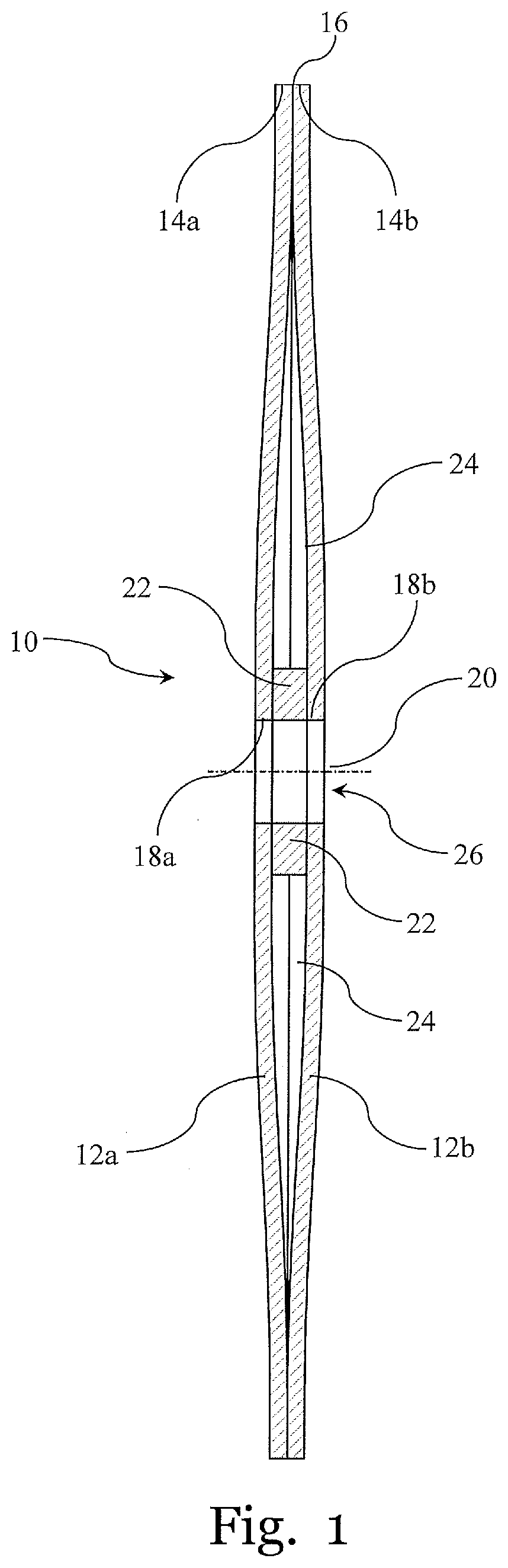
[0049]FIG. 1 shows a side view of a rotary cutting disc 10 according to an embodiment of the invention, which comprises two coaxial mutually opposed disc-shaped elements 12a and 12b. The disc-shaped elements 12a and 12b have a respective circumferential edge 14a and 14b. The circumferential edges 14a and 14b of the disc-shaped elements 12a and 12b are joined together forming a cutting edge 16 of the cutting disc 10. The disc-shaped elements 12a, 12b extend between a respective innermost circumferential edge 18a, 18b of the disc-shaped elements 12a, 12b and the respective ...


PUM


Abstract

A rotary cutting disc (10) comprising two coaxial mutually opposed disc-shaped elements (12a, 12b) each having a circumferential edge, wherein circumferential edges (14a, 14b) of the disc-shaped elements (12a, 12b) are joined together forming a cutting edge (16) of the cutting disc (10); wherein each of the disc-shaped elements (12a, 12b) comprises one or more at least partly curved elongated deformation lines (30), wherein the one or more deformation lines (30) have a radial distance from the centre (26) of the cutting disc (10) that increases along at least a part of the length of the deformation line (30). The rotary cutting disc (10) has an increased critical speed that allows improving the efficiency of a cutting operation with a cutting disc while maintaining acceptable levels of quality, cutting precision and safety.

Description

FIELD OF THE INVENTION[0001]The present invention is related to a cutting disc or diamond blade for cutting materials. More particularly, the present invention relates to a cutting disc with a novel configuration allowing for improved dynamical properties of the cutting disc in operation.BACKGROUND OF THE INVENTION[0002]Rotary cutting discs are widely employed in different fields of technology for cutting purposes. Cutting discs of relatively small dimensions in the submillimetric range are used for medical purposes, for example in the field of odontology. Cutting discs having diameters in a range from approximately 50 cm to as large as 2 m are used for instance in the fields of metallurgy, civil construction and wood processing for cutting a variety of materials.[0003]In a continued effort to increase the efficiency of cutting operations by cutting tools making use of cutting discs, manufacturers of cutting discs aim at an increasingly thinner shape thereof. Thinner cutting discs g...

Claims


Application Information

Patent Timeline
IPC IPC(8): B26D1/00
CPCB26D2001/0053B26D1/0006B26D2001/0033B23D61/026B26D2001/0046
Inventor MÄDER, MARCUS
Owner TECH UNIV MUNCHEN
Why Eureka
Try Eureka