Mechanical perforator

Active Publication Date: 2020-04-09
EXACTA FRAC ENERGY SERVICES INC
View PDF78 Cites 5 Cited by
  • Summary
  • Abstract
  • Description
  • Claims
  • Application Information

AI Technical Summary

Benefits of technology

The invention provides a mechanical perforator with cutting blades that can move from a retracted position to a cutting position and back again, allowing it to be relocated in a cased wellbore. This allows for more flexibility and reliability in use of the perforator.

Problems solved by technology

Although many different designs for mechanical casing perforators have been invented, none of them have gained widespread commercial use.

Method used


Image

  • Mechanical perforator
  • Mechanical perforator
  • Mechanical perforator

Examples


Embodiment Construction

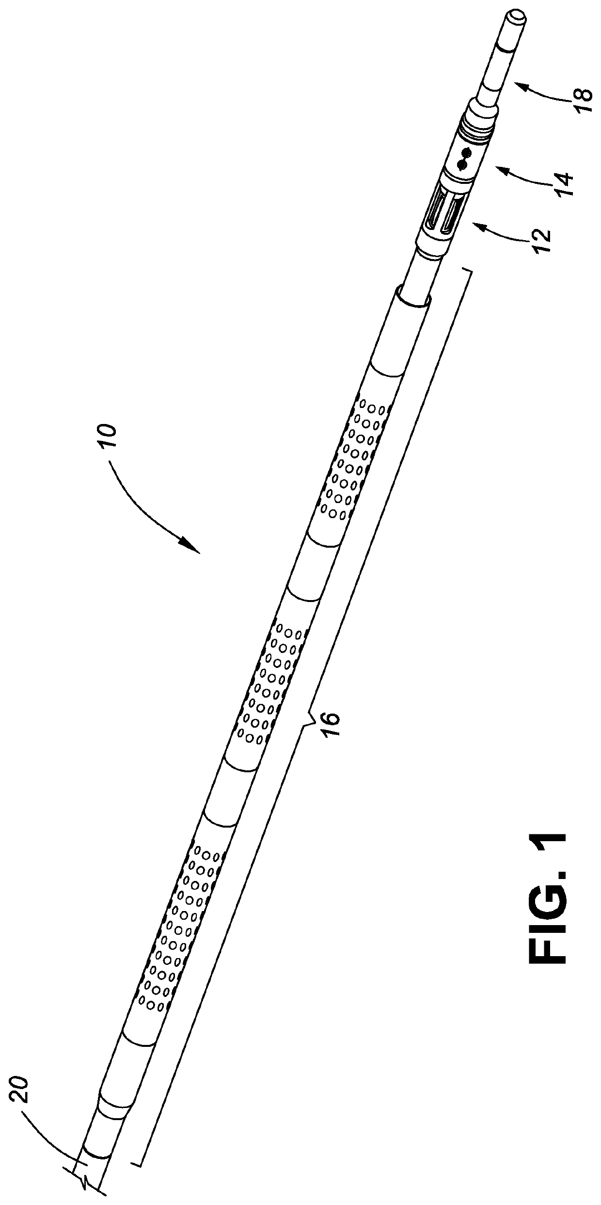
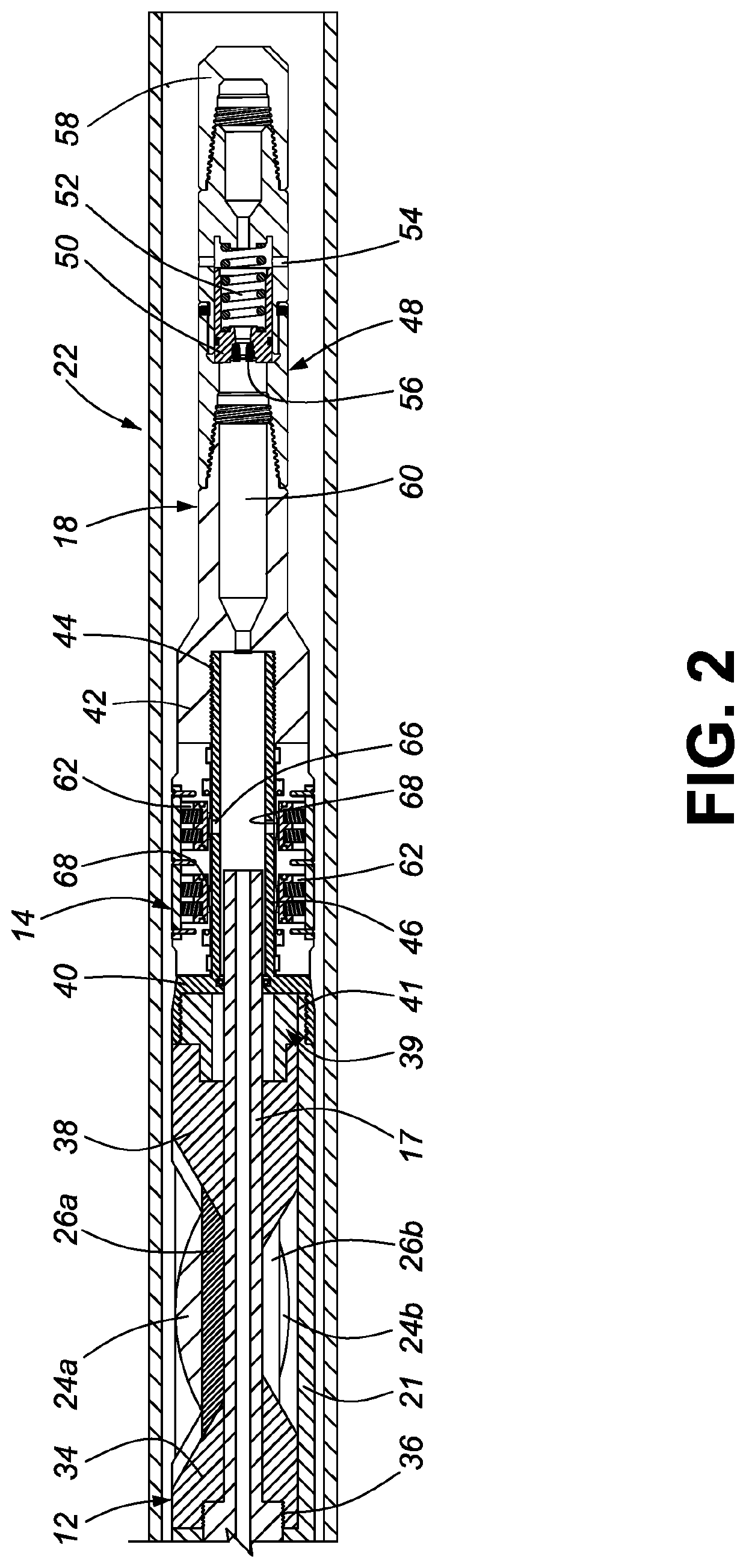
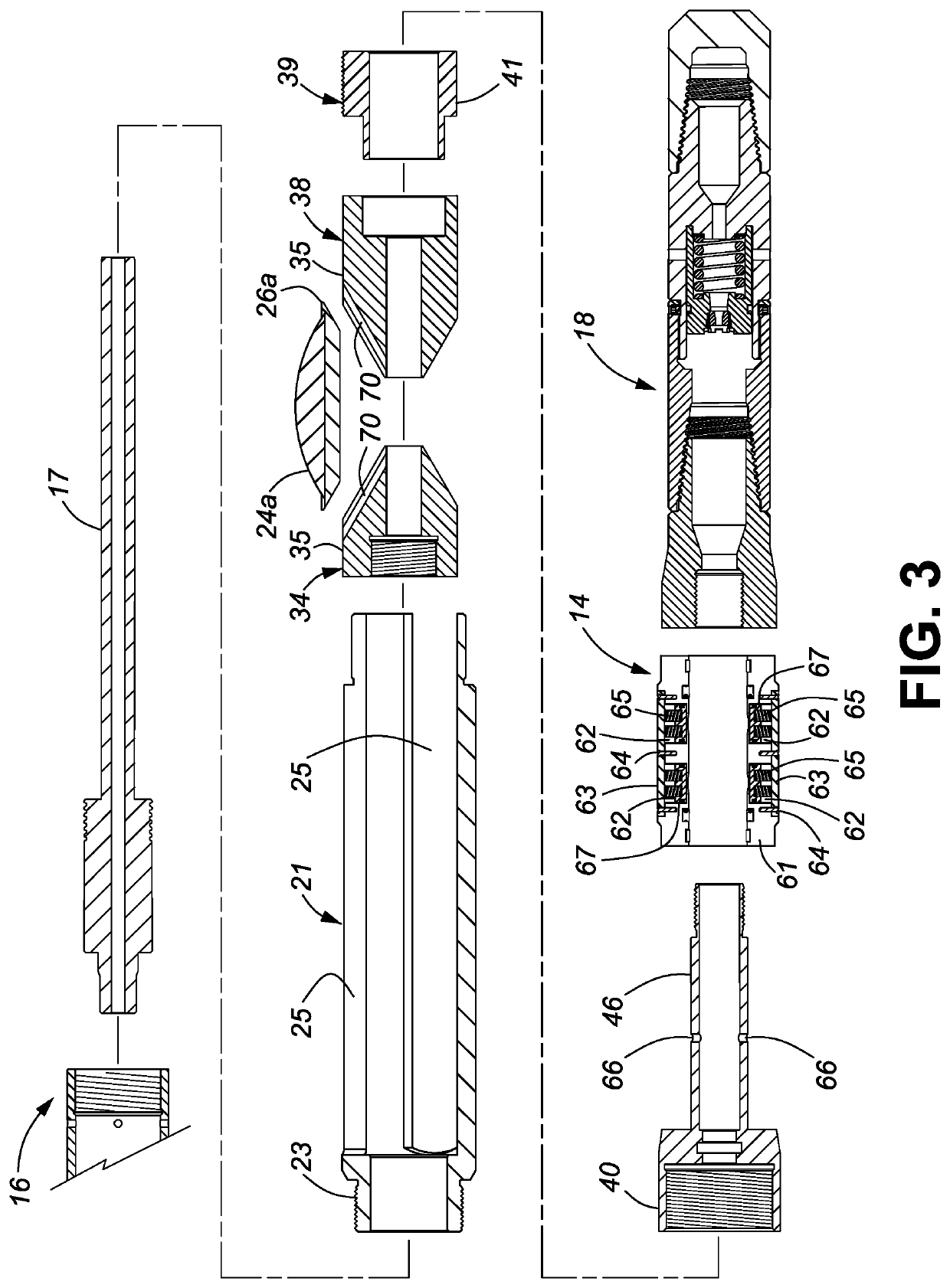
[0021]The invention provides a mechanical perforator with a plurality of perforator blades that simultaneously perforate a casing used to line a hydrocarbon well bore. Fluid pressure pumped into the mechanical perforator moves button slips to a deployed condition to bite the casing and lock the mechanical perforator in position for perforating the casing. A force multiplier moves the perforator blades from a retracted condition to a deployed condition in which the well casing is perforated, and back again to the retracted condition. After the casing is perforated, the mechanical perforator can be moved downhole to permit fracturing fluid to be pumped down an annulus of the casing string and through the perforation(s) in the casing joint to stimulate a section of the production zone behind the casing string. This process may be repeated until the entire production zone has been fractured and the well bore is ready for production. This mechanical perforator is useful in both well comp...


PUM


Abstract

A mechanical perforator includes a perforator module and a slip module. The perforator module has perforator blades that may be forced outwardly to perforate a well casing joint after slips of the slip module has been deployed to bite the well casing and anchor a lower end of the mechanical perforator in the well casing.

Description

CROSS REFERENCE TO RELATED APPLICATIONS[0001]This is the first application for this invention.FIELD OF THE INVENTION[0002]This invention, relates in general to well casing perforators and, in particular, to a novel, mechanical perforator for use in casing strings that line hydrocarbon well bores.BACKGROUND OF THE INVENTION[0003]Well casing perforators are known in the art and are used to perforate a “casing string” that is inserted into a drilled hydrocarbon well bore to provide a smooth liner in the well bore and prevent the wellbore from collapsing. Casing strings are typically assembled using lengths of plain pipe having pin-threaded ends called “casing joints”, which are interconnected using short tubular “casing collars” that have complimentarily box-threaded ends, though the casing joints may be box-threaded and the casing collars may be pin-threaded. The casing string is usually “cemented in” after it is run into a drilled well bore by pumping a cement slurry down through and...

Claims


Application Information

Patent Timeline
IPC IPC(8): E21B43/112E21B23/01
CPCE21B23/01E21B43/112E21B23/04115E21B29/005
Inventor HRUPP, JOZE JOHN
Owner EXACTA FRAC ENERGY SERVICES INC
Why Eureka
Try Eureka