
Distance measurement image pickup apparatus

Active Publication Date: 2020-04-09
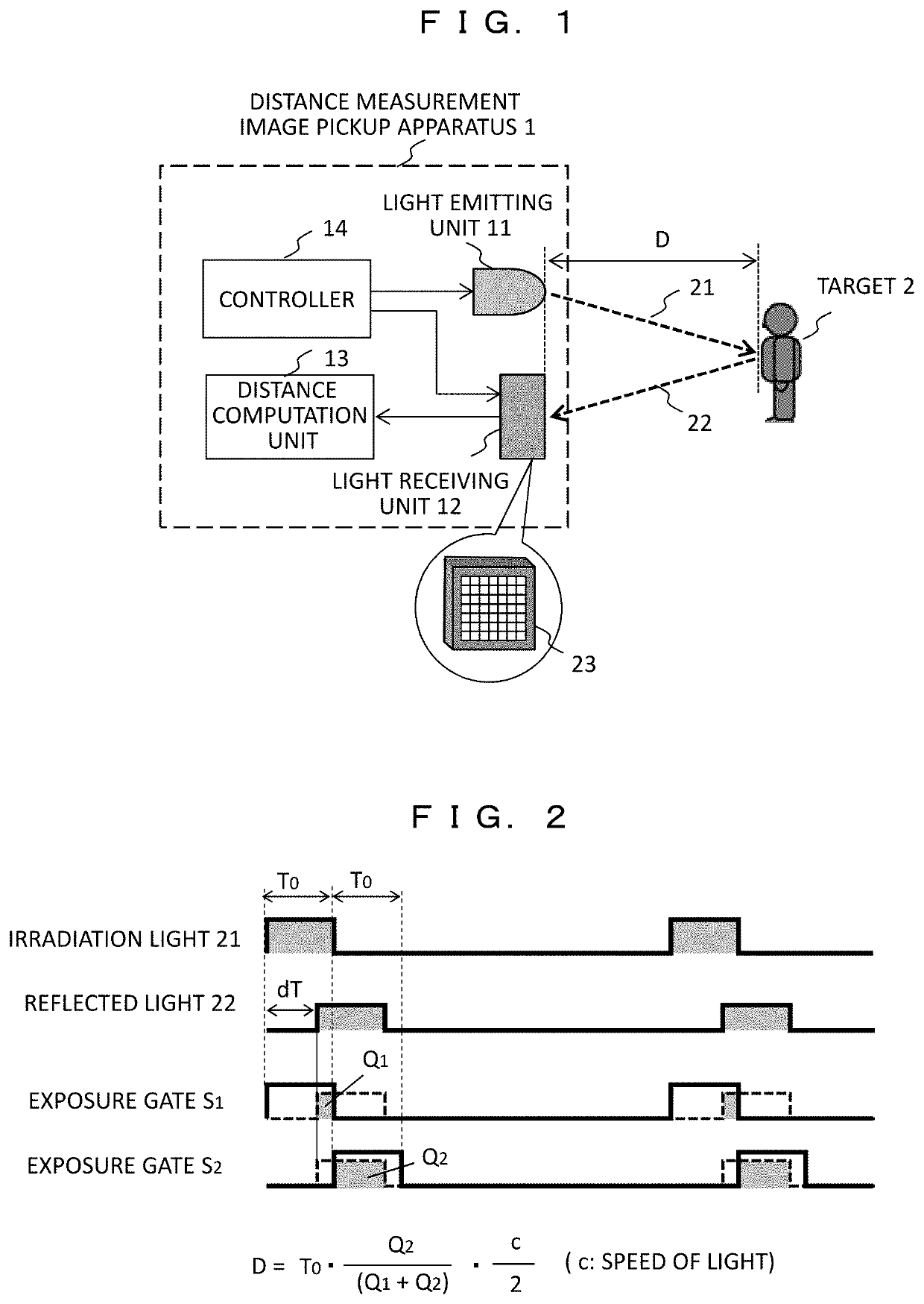
HITACHI-LG DATA STORAGE
View PDF0 Cites 2 Cited by
  • Summary
  • Abstract
  • Description
  • Claims
  • Application Information

AI Technical Summary

Benefits of technology

The invention aims to provide a distance measurement image pickup apparatus that can achieve high distance measurement accuracy and a wide distance measurement range while reducing errors caused by interference between multiple apparatuses.

Problems solved by technology

In the case of operating a plurality of distance measurement image pickup apparatuses in the same area, when irradiation light (or reflected light) other than an own apparatus becomes interference light and is exposed by the own apparatus, there is a problem that an error occurs in a distance measurement value.
However, applying this method to a configuration of WO 2017 / 022152 A is difficult due to the following reason.
However, as described below, it is necessary to increase the number of consecutive exposure gates, and there is a problem that a distance measurement error due to interference light increases.
Further, in the case of the method of changing the pulse width, since the distance measurement range is changed by changing the pulse width, the pulse width may not be largely changed, and it is difficult to reduce the distance measurement error due to the interference light.

Method used


Image

  • Distance measurement image pickup apparatus
  • Distance measurement image pickup apparatus
  • Distance measurement image pickup apparatus

Examples


example 1

[0055]FIG. 5A and FIG. 5B are diagrams illustrating light emission / exposure time charts in Example 1.

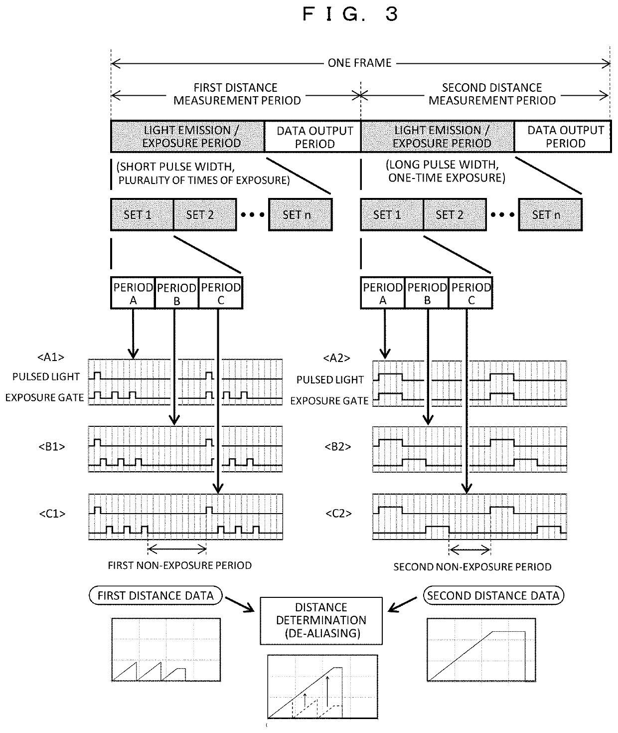
[0056]FIG. 5A illustrates light emission / exposure timing of the first distance measurement period. A short pulse width 1T is used as a light emission pulse, which is exposed by an exposure gate having the same width 1T (high modulation frequency). In the exposure period, exposure is performed in periods A, B, and C, timing of each of which is shifted by 1T. In each period, between one light emission pulse and a subsequent light emission pulse (reference symbol 35), the exposure gate is opened three times in a period 3T to perform repetitive exposure (reference symbols 31, 32, and 33), which corresponds to the “extended pulse scheme” introduced in this example. Then, a first non-exposure period 36 (here, a width of 10T) in which exposure is not performed after a last exposure gate (reference symbol 34) is closed until subsequent pulsed light (reference symbol 35) is emitted is provide...

example 2

[0099]In Example 2, a description will be given of an example in which the pulse width and the number of times of repetitive exposure are different from those in Example 1.

[0100]FIG. 14A and FIG. 14B are diagrams illustrating light emission / exposure time charts in Example 2.

[0101]FIG. 14A illustrates the light emission / exposure timing in the first distance measurement period. A short pulse width 1T is used for the light emission pulse. During the exposure period, exposure is performed in the periods A, B, and C, timing of each of which is shifted by 1T. In each period, the exposure gate is opened twice in a period 3T for one light emission pulse and repetitive exposure is performed (reference symbols 81, 82, and 83). That is, in this case, the “extended pulse scheme” is used. Then, from when a last exposure gate (reference symbol 84) is closed until subsequent pulsed light (reference symbol 85) is emitted, a first non-exposure period 86 (here, a width of 13T) in which exposure is no...


PUM


Abstract

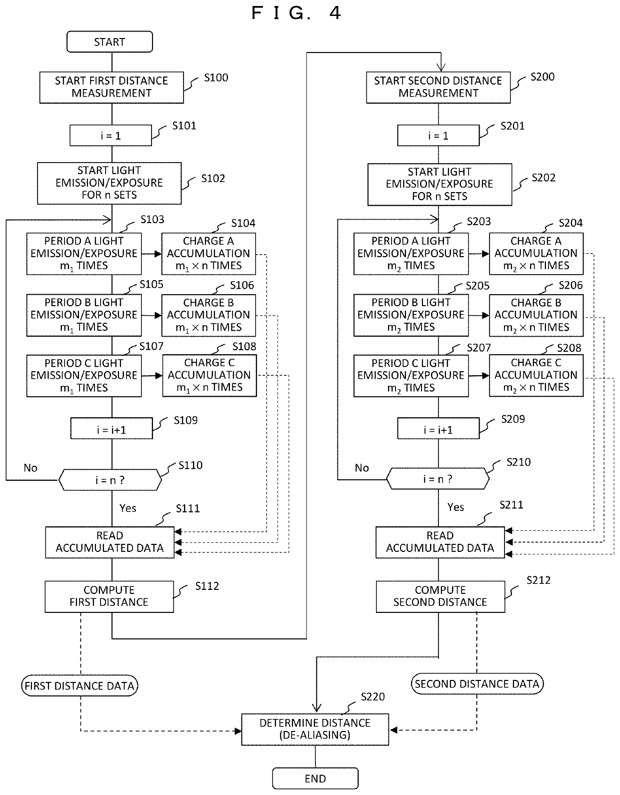
A distance measurement image pickup apparatus has two measurement periods. In a first distance measurement period, short pulsed light (1T) is irradiated, and exposure is performed in a plurality of exposure periods (A, B, and C) in which exposure timings are shifted. In each exposure period, an exposure gate is opened a plurality of times to perform repetitive exposure, and a first non-exposure period is provided from when a last exposure gate is closed until subsequent pulsed light is irradiated. In a second distance measurement period, long pulsed light (4T) is irradiated, and exposure is performed in a plurality of exposure periods (A, B, and C) in which exposure timings are shifted. In each exposure period, exposure is performed by opening the exposure gate only once, and a second non-exposure period is provided from when a last exposure gate is closed until subsequent pulsed light is irradiated.

Description

CLAIM OF PRIORITY[0001]The present application claims priority from Japanese patent application serial No. JP 2018-187826, filed on Oct. 3, 2018, the content of which is hereby incorporated by reference into this application.BACKGROUND OF THE INVENTION(1) Field of the Invention[0002]The present invention relates to a distance measurement image pickup apparatus that measures a distance to a target by a time of flight of light.(2) Description of the Related Art[0003]A time of flight (TOF) method of measuring a distance by a time of flight until irradiation light is reflected by a target and returns has been known as a method of measuring a distance to a target. Specifically, exposure is performed by a plurality of exposure gates in which exposure timings are shifted with respect to a light emission timing of intensity-modulated irradiation light, and a delay time of reflected light with respect to the irradiation light is calculated from the exposure amount accumulated in each exposur...

Claims


Application Information

Patent Timeline
IPC IPC(8): G01S17/10H04N5/235
CPCG01S7/4865H04N5/2353G01S17/10H04N5/372G01S17/894H04N23/60G01S7/4815G01S7/483G01S7/487G01S17/04G01S17/18G01S17/32G01S17/42H01L27/146H01L27/14601H04N23/73H04N25/71
Inventor KAMISADA, TOSHIMASAMASUDA, KOZOSUGIYAMA, HISATAKASHINTANI, TOSHIMICHI
Owner HITACHI-LG DATA STORAGE
Learn More