Device and method for measuring object distance

A technology for measuring signals and measuring units, applied in the field of distance measurement, can solve problems such as interference and strong background noise that affect the accuracy of distance measurement, ground and other background obstacles other than target obstacles, etc., and achieve high reliability. , the effect of simple structure

Active Publication Date: 2015-09-23
CHERY AUTOMOBILE CO LTD
View PDF2 Cites 0 Cited by
  • Summary
  • Abstract
  • Description
  • Claims
  • Application Information

AI Technical Summary

Problems solved by technology

[0006] Although the above solution solves the problem of the distance measurement blind area, the distance measurement accuracy of the laser distance measurement system will also be interfered by the external environmental noise of the vehicle (that is, the ground and other background obstacles other than the target obstacle, etc.). The solution is to use a band-pass filter lens to reduce the interference of external environmental noise. The band-pass filter lens only allows the light in the laser wavelength range emitted by the laser to pass through. The divergence angle of the pulse signal is compressed to only one or several milliradians, so that the laser pulse signal will form a small spot when it is irradiated on the object, so this laser pulse signal is called a spot pulse) and the measurement accuracy is higher, but , for some special applications, such as increasing the detection area, the laser pulse signal emitted by the laser diverges into a large angle to detect whether there is a target obstacle within the angle range. At this time, the The field of view of the condensing lens is very large, so that part of the laser pulse signal emitted by the laser is projected on the target obstacle, and the other part is projected on the ground or other background obstacles in the area where the target obstacle is located. When the light projected onto the ground or other background obstacles passes through the condenser lens and is received by the photodetector, it forms a strong background noise.
In addition, since the sunlight spectrum covers near-infrared wavelengths, when the wavelength of the laser pulse signal emitted by the laser is within the solar infrared spectrum range, the sunlight infrared spectrum components in the same band as the laser pulse signal emitted by the laser cannot be detected. Filtered by the band-pass filter lens, it also forms a strong background noise, which affects the distance measurement accuracy

Method used


Image

  • Device and method for measuring object distance
  • Device and method for measuring object distance
  • Device and method for measuring object distance

Examples


Embodiment 1

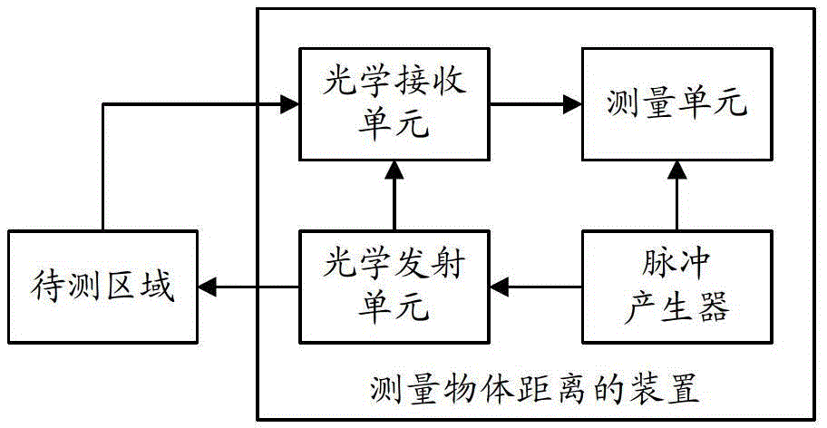
[0062] Such as figure 1 As shown, this embodiment provides a device for measuring the distance of an object, including a pulse generator, an optical transmitting unit, an optical receiving unit, and a measuring unit.

[0063] The pulse generator is used to sequentially send electrical pulses to the optical emission unit at a fixed frequency, that is, to sequentially send electrical pulses to the optical emission unit at the same time interval.

[0064] The optical transmitting unit is used to send an optical pulse signal in real time each time it receives an electrical pulse from the pulse generator. The optical pulse signal includes two parts, one part of the optical pulse signal directly enters the optical receiving unit as a reference signal, and the other part The light pulse signal is sent to the area to be measured as a measurement signal, and enters the optical receiving unit after being reflected by the area to be measured. That is to say, each electrical pulse sent b...

Embodiment 2

[0083] This embodiment provides a device for measuring the distance of an object. in,

[0084] The optical transmitting unit includes a laser and a transmitting optical lens, and the transmitting optical lens is used for reflecting a part of the light pulse emitted by the laser to the inner optical path photodetector as a reference signal.

[0085] The optical receiving unit includes an inner optical path photodetector, one or more outer optical path photodetectors, and one or more outer optical path condensing lenses, and each outer optical path condensing lens corresponds to an outer optical path photodetector.

[0086] A part of the optical pulse signal emitted by the laser is directly received by the photodetector in the inner optical path as a reference signal, and the other part is sent to the area to be tested as a measurement signal. The area to be tested is one or more, and each area to be tested is Each area corresponds to an outer optical path photodetector, and th...

Embodiment 3

[0107] Such as Figure 7 As shown, the difference between this embodiment and embodiment 2 is:

[0108] The optical receiving unit 3 also includes an infrared light-emitting diode 34, and the inner optical path photodetector 31 is used to send the reference signal received by it to the infrared light-emitting diode 34, and excite the infrared light-emitting diode 34 to emit infrared light at the pulse frequency of the reference signal. The light pulse signal is sent to the outer optical path photodetector 32; the outer photodetector 32 is used to send the measurement signal reflected back from the area to be measured it receives and the infrared light pulse signal with the same pulse frequency as the reference signal to the measurement as a reference signal unit.

[0109] Since the optical pulse signal (including the reference signal and the measurement signal) needs to be processed before it can be sent to the measurement unit, the inner / outer optical path photodetectors hav...


PUM


Abstract

The invention provides a device for measuring an object distance. The device comprises a pulse generator, an optical emission unit, an optical receiving unit and a measurement unit, wherein the pulse generator is used for sequentially transmitting electrical pulses to the optical emission unit at fixed frequency; the optical emission unit is used for transmitting optical pulse signals in real time every time when receiving the electrical pulses, a part of the optical pulse signals directly enter the optical receiving unit as reference signals, and the other part of the optical pulse signals enter the optical receiving unit after being reflected through an area to be detected as measurement signals; the optical receiving unit is used for transmitting the reference signals and the measurement signals to the measurement unit in real time; and the measurement unit is used for subtracting the measurement signal when a target obstacle does not exist at the last moment from the measurement signal when the target obstacle exists in the area to be detected to obtain a background interference-free measurement signal, and obtaining a distance with the target obstacle in real time according to the background interference-free measurement signal and the reference signal. Correspondingly, the invention provides a method for measuring the object distance. According to the device and the method, the influence of temperature and background interference signals on the distance measurement accuracy can be reduced or eliminated, and the distance measurement accuracy is higher.

Description

technical field [0001] The invention belongs to the technical field of distance measurement, and in particular relates to a device and a method for measuring the distance of an object. Background technique [0002] A laser distance measurement system generally includes a pulse generator, an optical lens, a laser and a photoelectric detector. The laser distance measurement system uses a laser as a light source for distance measurement. Its working principle is: the pulse generator sends out an electrical trigger signal pulse ( That is, electric pulse) to the laser, triggering the laser to send out a light pulse signal (that is, a laser pulse signal), the light pulse signal is reflected by the target obstacle and then received by the photoelectric detector, then the theoretical distance between the laser distance measurement system and the target obstacle The distance is half of the product of the round-trip time of the light pulse signal and the speed of light. The round-trip...

Claims


Application Information

Patent Timeline
Patent Type & Authority Patents(China)
IPC IPC(8): G01S17/10G01S7/487
Inventor 徐海峰刘翔宇
Owner CHERY AUTOMOBILE CO LTD
Why Eureka
Try Eureka