Calibration circuit and method

A technology for calibrating circuits and circuits, applied in electrical components, impedance networks, etc., can solve problems affecting the position of zero and pole points, process deviation of resistors and capacitors, increasing the cost and power consumption of calibration circuits, etc.

Pending Publication Date: 2019-05-10
广州全盛威信息技术有限公司 +1
View PDF7 Cites 5 Cited by
  • Summary
  • Abstract
  • Description
  • Claims
  • Application Information

AI Technical Summary

Problems solved by technology

[0002] In analog integrated circuits, resistor-capacitor RC filters are usually used in integrated circuits to control the frequency of poles and zeros. However, in modern semiconductor manufacturing processes, resistors and capacitors will vary greatly with the process. This in turn affects the position of the zero and pole points, therefore, the RC must be calibrated in the application
In the conventional RC calibration technology, the calibration result is greatly affected by the parasitic capacitance and the DC offset dc offset, which affects the calibration accuracy
Even if some schemes can reduce the influence of parasitic capacitance on the calibration result by using an active integrator circuit, due to the use of an operational amplifier, the cost and power consumption of the calibration circuit will be increased, and there is still a dc offset that affects the calibration accuracy

Method used


Image

  • Calibration circuit and method
  • Calibration circuit and method
  • Calibration circuit and method

Examples


example 1

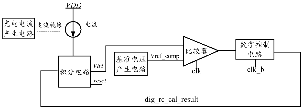
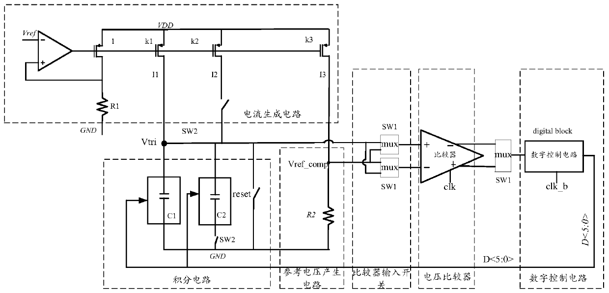
[0046] see Figure 5 , when the first capacitor and the second capacitor are variable capacitors, the first resistor and the second resistor are fixed resistors. Set the proportions of the current mirrors to k1, k2, and k3 respectively, thereby generating three currents I1, I2, and I3; setting I1=I2, then I1=Vref*k1 / R1, Vref_comp=Vref*k3*R2 / R1; It can be seen that once R1 and R2 are determined, Vref_comp has nothing to do with the resistance and capacitance. Next, the frequency of the clock source can be set as a period of 2Ts and a duty cycle of 50%, so it can be seen that the charging time of the capacitor is Ts.

[0047] When SW2 is disconnected and SW1 is disconnected, the charging current is only I1, and there is only variable capacitor C1 in the integrating circuit, and the charging voltage is Vtri=I1*Ts / C1, that is, Vtri=Vref*k1*Ts / (R1*C1 ), that is, when Vtri is a fixed value, R1*C1 is a constant. The positive input of the voltage comparator is Vtri, and the reverse...

example 2

[0059] see Figure 6 , when the first resistor R1 and the second resistor R2 are variable resistors, the first capacitor and the second capacitor are fixed capacitors, and the ratios of the current mirrors are set to k1, k2, k3 respectively, thereby generating three currents I1, I2, I3; set I1=I2, then I1=Vref*k1 / R1, Vref_comp=Vref*k3*R2 / R1; when the ratio of R1 to R2 remains unchanged, Vref_comp is still independent of the resistance and capacitance. Next, the frequency of the clock source can be set as a period of 2Ts and a duty cycle of 50%, so it can be seen that the charging time of the capacitor is Ts.

[0060] Subsequently, according to the scheme described in Example 1, the calibration digital control signals in the four states of SW2 open and SW1 open, SW2 closed and SW1 open, SW2 open and SW1 closed, and SW2 closed and SW1 closed are obtained respectively. , and generate a calibration result finally obtained by the calibration circuit according to the calibration di...


PUM


Abstract

The embodiment of the invention discloses a calibration circuit and method. The method comprises the following steps: determining a plurality of calibration states according to a charging current, anaccess state of a capacitor in an integrating circuit and an input end input signal state of a voltage comparator; In each calibration state, enabling the digital control circuit to generate a digitalcontrol signal according to the voltage comparison signal output by the voltage comparator; In each calibration state, when the reference voltage and the charging voltage are in an equal or set difference range under the control of the digital control signal, determining a calibration digital control signal corresponding to each calibration state; And obtaining a final calibration signal from thecalibration digital control signals corresponding to all the calibration states according to a preset processing strategy.

Description

technical field [0001] The invention relates to the technical field of electronic circuits, in particular to a calibration circuit and method. Background technique [0002] In analog integrated circuits, resistor-capacitor RC filters are usually used in integrated circuits to control the frequency of poles and zeros. However, in modern semiconductor manufacturing processes, resistors and capacitors will vary greatly with the process. This in turn affects the positions of the zero and pole points, so the RC must be calibrated in the application. In the conventional RC calibration technology, the calibration result is greatly affected by the parasitic capacitance and the DC offset dc offset, thus affecting the calibration accuracy. Even if some schemes can reduce the influence of parasitic capacitance on the calibration result by using an active integrator circuit, the cost and power consumption of the calibration circuit will be increased due to the use of an operational amp...

Claims


Application Information

Patent Timeline
IPC IPC(8): H03H1/02
CPCY02E60/10
Inventor 郑雷李艳辉张小磊
Owner 广州全盛威信息技术有限公司
Why Eureka
Try Eureka