Dc-dc converter multilayer coil array and dc-dc converter

a converter and coil array technology, applied in the direction of electric variable regulation, process and machine control, instruments, etc., can solve the problems of increasing the risk of short circuit generation between adjacent coil conductors, and the need for reducing the potential difference, so as to suppress the generation of short circuits and reduce the potential difference

Active Publication Date: 2020-04-09
MURATA MFG CO LTD
View PDF2 Cites 0 Cited by
  • Summary
  • Abstract
  • Description
  • Claims
  • Application Information

AI Technical Summary

Benefits of technology

[0006]Accordingly, the present disclosure provides a DC-DC converter multilayer coil array that can reduce a potential difference between ad

Problems solved by technology

However, a potential difference generated between two coils in a small-sized surface-mount coil array component may be problem and there is a demand for this potential difference

Method used


Image

  • Dc-dc converter multilayer coil array and dc-dc converter
  • Dc-dc converter multilayer coil array and dc-dc converter
  • Dc-dc converter multilayer coil array and dc-dc converter

Examples


Embodiment Construction

[0035]Hereafter, a multilayer coil array according to an embodiment of the present disclosure will be described in detail while referring to the drawings. The embodiment described hereafter is for illustrative purposes and the present disclosure is not limited to the embodiment described hereafter. Unless specifically stated otherwise, it is not intended that scope of the present disclosure be limited to the dimensions, materials, shapes, relative arrangements, and so forth of constituent components described hereafter and these are merely explanatory examples. In addition, the sizes, shapes, positional relationships, and so forth of the constituent elements illustrated in the drawings may be exaggerated for the sake of clear explanation.

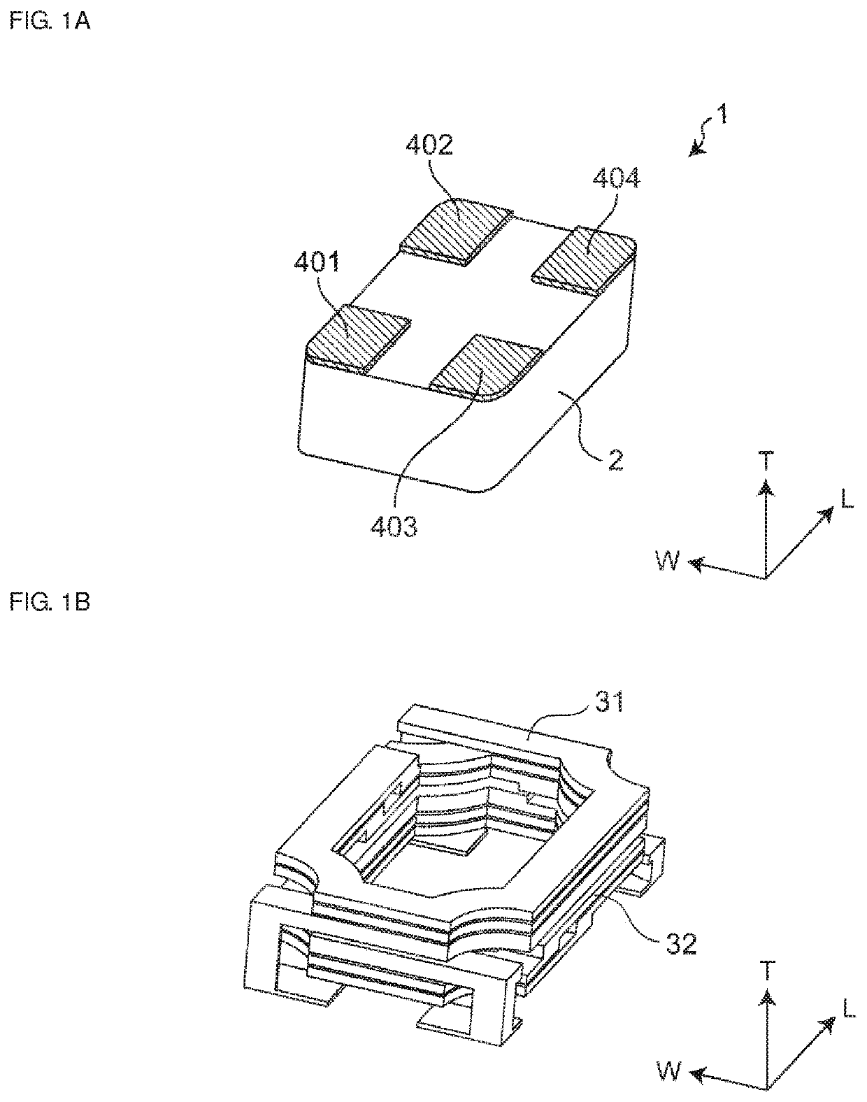
[0036]A multilayer coil array 1 according to an embodiment of the present disclosure is illustrated in FIGS. 1A and 1B. FIG. 1A is a perspective view in which the multilayer coil array 1 of the embodiment of the present disclosure is seem from the b...


PUM


Abstract

A multilayer coil array includes an element body; first and second built-in coils; and first to fourth outer electrodes provided on the element body. A non-magnetic layer is provided between the first and second coils. An end of the first coil extending from the coil conductor closest to the second coil among the plurality of coil conductors of the first coil is connected to the first outer electrode and another end of the first coil is connected to the second outer electrode. An end of the second coil extending from the coil conductor closest to the first coil among the plurality of coil conductors of the second coil is connected to the third outer electrode and another end portion of the second coil is connected to the fourth outer electrode. The first and third outer electrodes are connected to output terminals of a switching element of a DC-DC converter.

Description

CROSS-REFERENCE TO RELATED APPLICATION[0001]This application claims benefit of priority to Japanese Patent Application No. 2018-190200, filed Oct. 5, 2018, the entire content of which is incorporated herein by reference.BACKGROUNDTechnical Field[0002]The present disclosure relates to a DC-DC converter multilayer coil array and a DC-DC converter.Background Art[0003]Japanese Unexamined Patent Application Publication No. 2016-186963 discloses a coil component of the related art. That is, Japanese Unexamined Patent Application Publication No. 2016-186963 discloses a multilayer electronic component in which magnetic layers and conductor patterns are stacked on top of one another and a coil is formed inside the resulting multilayer body by connecting the conductor patterns between the magnetic layers. The magnetic layers are formed of a metal magnetic material. At least one extending conductor pattern of the coil is connected to an outer terminal formed on a bottom surface of the multilay...

Claims


Application Information

Patent Timeline
IPC IPC(8): H01F27/28H02M3/158H02M1/088H01F27/24H01F27/29H01F41/04
CPCH02M3/158H01F27/29H01F27/24H02M1/088H01F2027/2809H01F27/2804H01F41/041H01F27/324H01F27/292H01F41/046H01F41/10H01F41/125H02M3/28H01F17/0013H01F17/04H01F2017/0066H01F27/255H01F41/043H02M3/1584Y02B70/10H02M1/0064
Inventor SATO, MITSUHIROKAWABATA, RYOHEI
Owner MURATA MFG CO LTD
Why Eureka
Try Eureka