

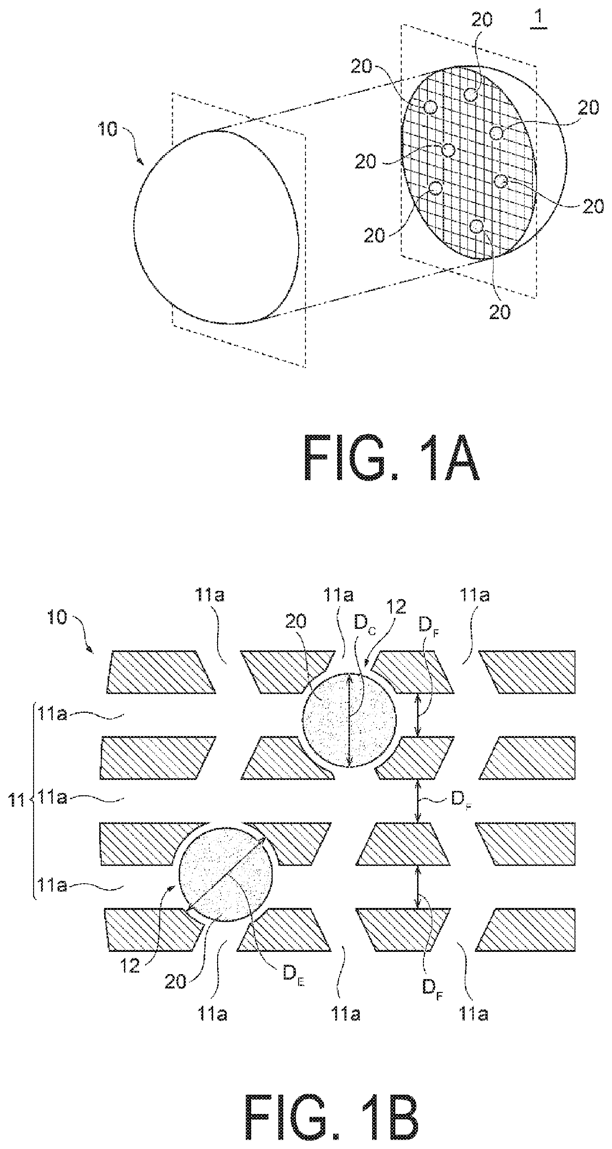
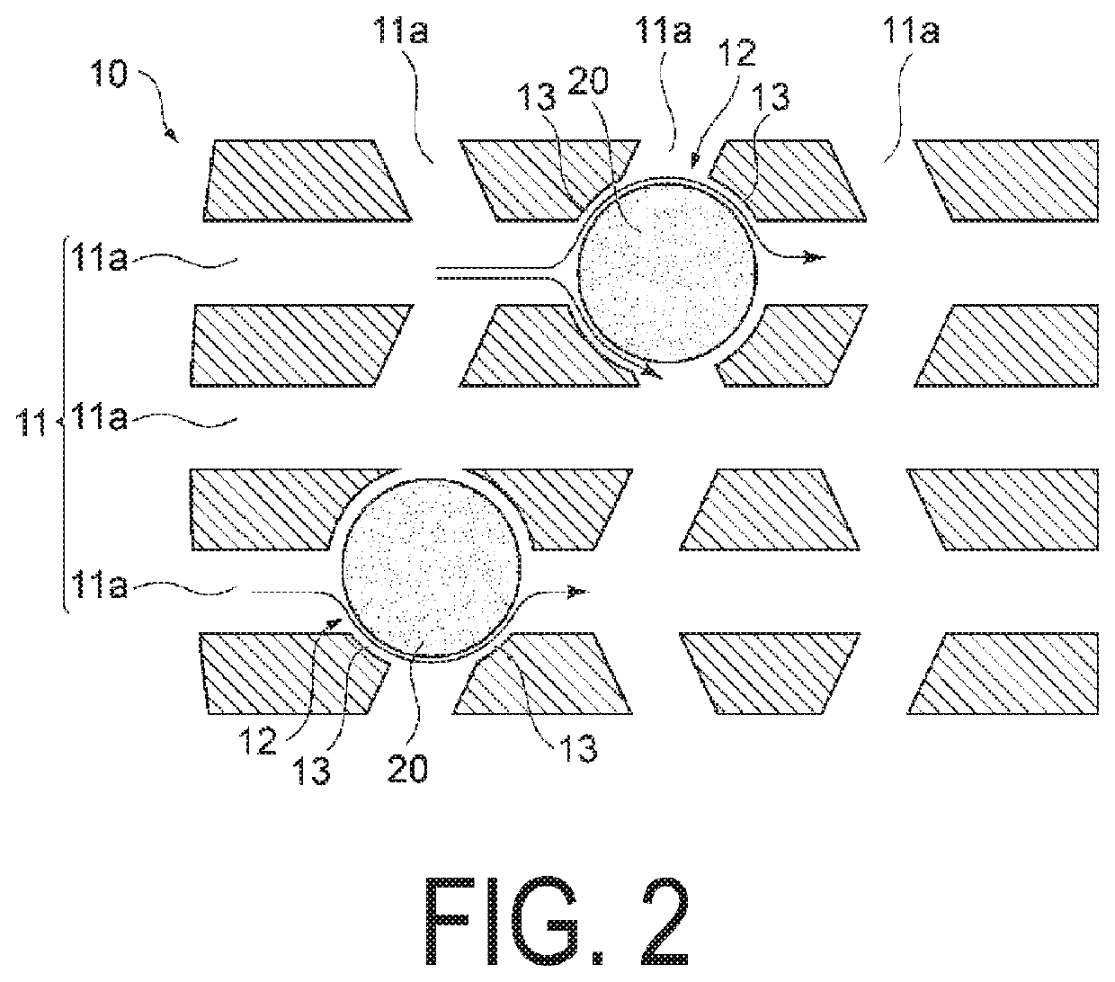
Structured photocatalyst, structured photocatalyst composition, photocatalyst coated material, method for producing structured photocatalyst, and method for decomposing aldehydes
a photocatalyst and composition technology, applied in the direction of physical/chemical process catalysts, molecular-sieve silica-polymorphs, separation processes, etc., can solve the problems of relatively large size of titanium oxide mesocrystals and inability to easily aggregate, so as to achieve favorable photocatalytic functionality and prevent aggregation
- Summary
- Abstract
- Description
- Claims
- Application Information
AI Technical Summary
Benefits of technology
Problems solved by technology
Method used
Image

Examples
examples 1 to 96
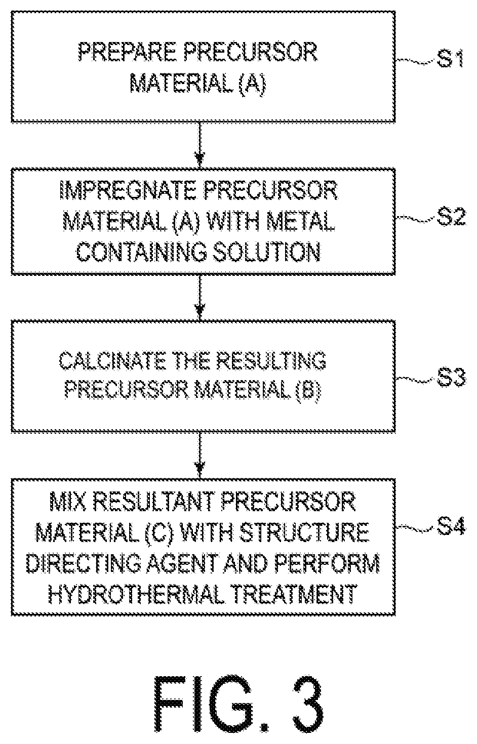
Synthesis of Precursor Material (A)
[0163]A silica agent (tetraethoxysilane (TEOS), available from Wako Pure Chemical Industries, Ltd.) was mixed with a surfactant serving as a molding agent to prepare a mixed aqueous solution. The pH was adjusted as appropriate, and a hydrothermal treatment was performed at from 80 to 350° C. for 100 hours in a sealed container. Subsequently, the produced precipitate was filtered out, washed with water and ethanol, and was further subjected to a calcination treatment in air at 600° C. for 24 hours to obtain the precursor material (A) of the types and the pore diameters listed in Tables 1 and 2. Note that the following surfactants were used depending on the types of the precursor material (A) (“the type of precursor material (A): surfactant”).[0164]MCM-41: Hexadecyltrimethylammonium bromide (CTAB) (available from Wako Pure Chemical Industries, Ltd.)[0165]SBA-1: Pluronic P123 (available from BASF)
Production of Precursor Materials (B) and (C)
[0166]Next...
PUM
| Property | Measurement | Unit |
|---|---|---|
| particle size | aaaaa | aaaaa |
| inner diameter | aaaaa | aaaaa |
| specific surface area | aaaaa | aaaaa |
Abstract
Description
Claims
Application Information