Lubricating oil discharge and filling structure

Inactive Publication Date: 2020-04-16
ROKI CO LTD
View PDF0 Cites 1 Cited by
  • Summary
  • Abstract
  • Description
  • Claims
  • Application Information

AI Technical Summary

Benefits of technology

The present invention provides a lubricating oil discharge and filling structure of an oil pan that can achieve space saving by using an uniaxial structure. The structure allows for reliable and easy discharge and filling of lubricating oil without varying the height of the oil levels. Additionally, a falling-off prevention device is included to ensure the oil level adjustment is accurate. The structure includes a lubricating oil discharge hole, a cylindrical lubricating oil amount adjustment plug, and a sealing wall to prevent lubricating oil from leaking. The plug can abut on an abutment portion in the oil amount adjustment passage, ensuring constant oil levels and reliable discharge without the need for alignment.

Problems solved by technology

However, according to the enclosed amount adjustment mechanism of lubricating oil as described above, there arise the problem that work is complicated because it is necessary to detach and attach the bolts that respectively close the lubricating oil discharge hole and the lubricating oil amount adjustment hole, and the problem that reduction in size of the oil pan, reduction in size of the automatic transmission by extension cannot be achieved because it is necessary to form the lubricating oil discharge hole and the lubricating oil amount adjustment hole in the oil pan.
However, according to a configuration of the aforementioned conventional oil pan, the lubricating oil cannot be smoothly discharged unless the side hole of the lubricating oil filling collar and the side hole of the tubular member are reliably aligned with each other at the time of discharge of the lubricating oil, whereas the lubricating oil filling collar and the tubular member are internal structure components of the oil pan, so that it is impossible to confirm that the positions of the side holes are reliably aligned with each other visually, and there arises the problem that working efficiency is low.

Method used


Image

  • Lubricating oil discharge and filling structure
  • Lubricating oil discharge and filling structure
  • Lubricating oil discharge and filling structure

Examples


first embodiment

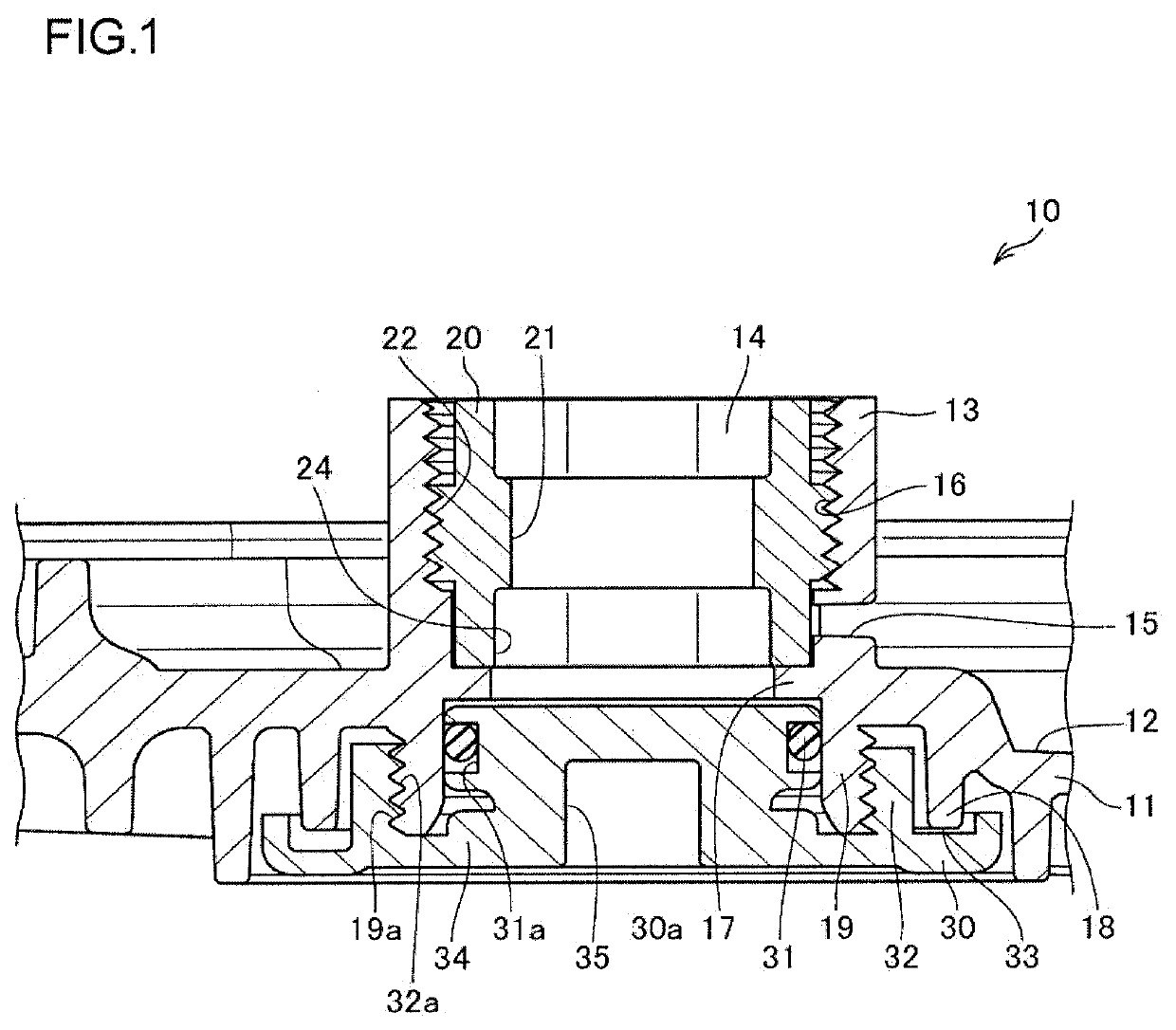
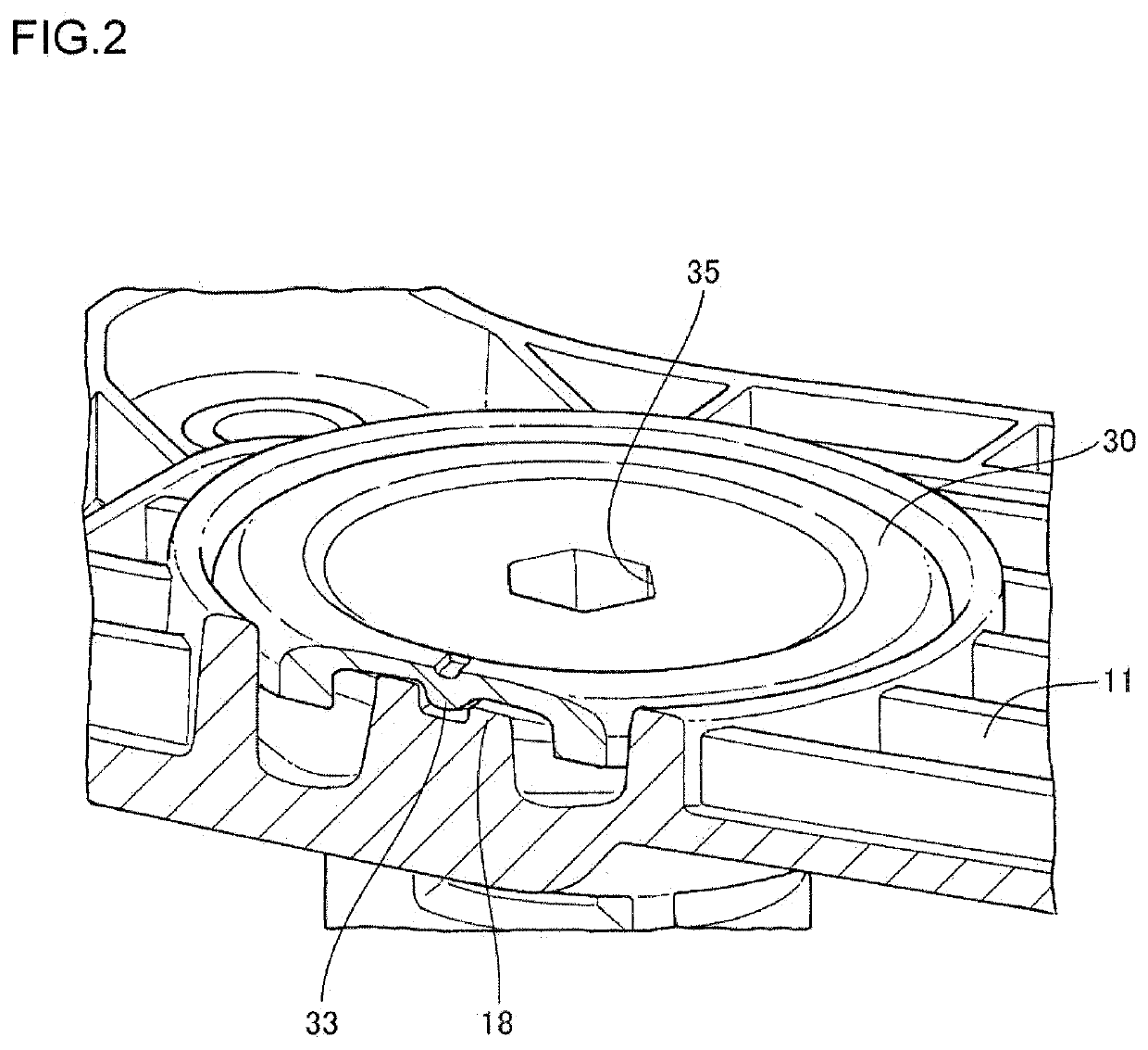
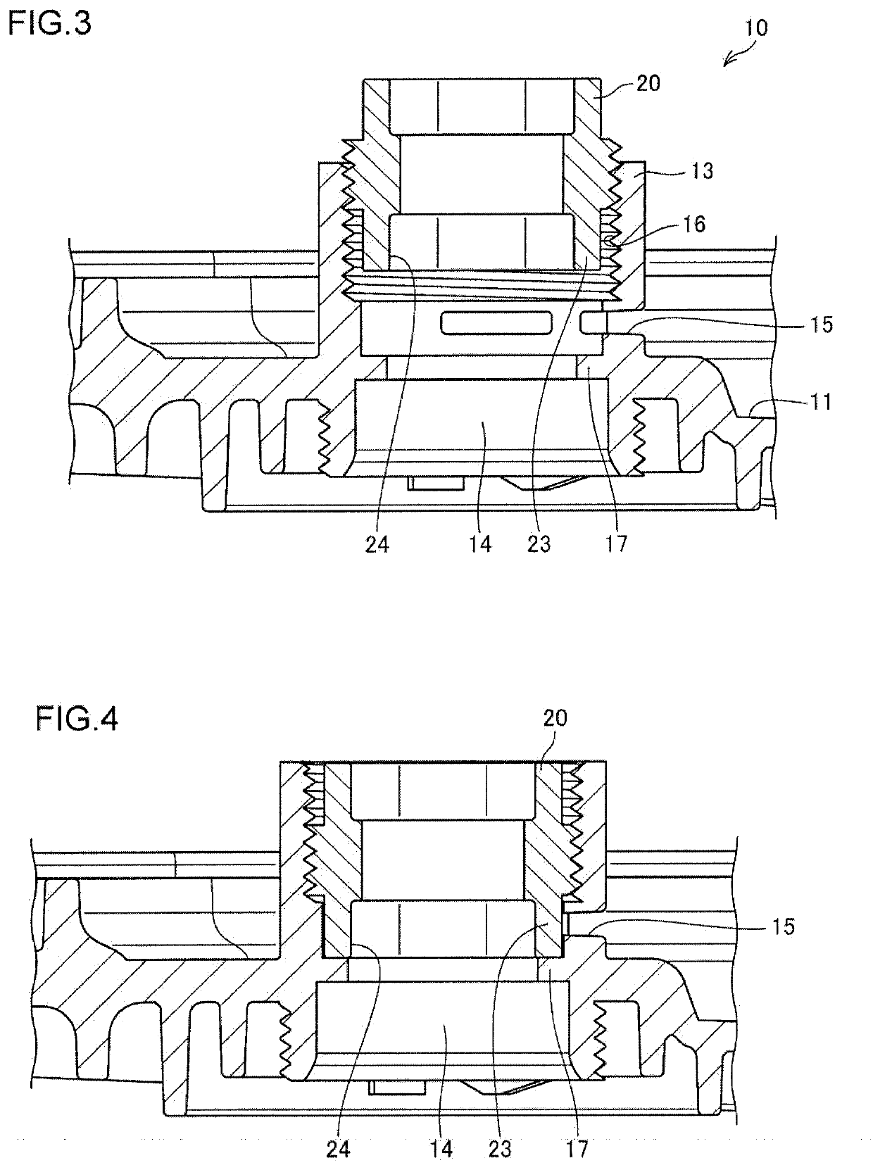
[0029]FIG. 1 is a sectional view for explaining a configuration of a lubricating oil discharge and filling structure according to a first embodiment of the present invention. FIG. 2 is a partial sectional view for explaining the configuration of the lubricating oil discharge and filling structure according to the first embodiment of the present invention. FIG. 3 is a sectional view for explaining a configuration at a time of oil discharge of the lubricating oil discharge and filling structure according to the first embodiment of the present invention. FIG. 4 is a sectional view for explaining a configuration at a time of filling of the lubricating oil discharge and filling structure according to the first embodiment of the present invention. FIG. 5 is a sectional view for explaining a configuration of a falling-off prevention device of the lubricating oil discharge and filing structure according to the first embodiment of the present invention. FIG. 6 is a sectional view for explain...

second embodiment

[0051]In the lubricating oil discharge and filling structure 10 according to the first embodiment described above, explanation is made about the case where the lubricating oil amount adjustment plug 20 is screwed into the screw groove 16 which is formed on the inner circumferential surface of the lubricating oil amount adjustment passage 14, and the lubricating oil amount adjustment plug 20 is mounted movably along the lubricating oil amount adjustment passage 14. In a lubricating oil discharge and filling structure 10′ of a second embodiment that will be described next, explanation is made about an example of a lubricating oil amount adjustment plug 53 having a mode different from the first embodiment. Note that same or similar members as or to those in the case of the aforementioned first embodiment will be assigned with the same reference signs and explanation thereof will be omitted.

[0052]FIG. 7 is a perspective view showing the lubricating oil discharge and filling structure ac...


PUM


Abstract

A lubricating oil discharge and filling structure of an oil pan including a cylindrical lubricating oil amount adjustment wall vertically provided from a bottom surface of the oil pan, and having a lubricating oil amount adjustment passage communicating with an outside of the oil pan, formed on an inner periphery. The lubricating oil amount adjustment wall has a lubricating oil discharge hole formed in a lower part, to the lubricating oil amount adjustment passage, a cylindrical lubricating oil amount adjustment plug in which a communication hole that communicates with the lubricating oil amount adjustment passage is formed is assembled movably along the lubricating oil amount adjustment passage. The lubricating oil amount adjustment plug includes a screw portion that screws into a screw groove formed in the lubricating oil amount adjustment passage, and a sealing wall that seals discharge of the lubricating oil from the lubricating oil discharge hole.

Description

BACKGROUND OF THE INVENTIONField of the Invention[0001]The present invention relates to an oil pan that is mounted to a lower end of a mechanical device, and particularly relates to an oil pan having an adjustment mechanism that can adjust an enclosing amount of lubricating oil that is enclosed in an automatic transmission or the like.Description of the Related Art[0002]Conventionally, lubricating oil has been enclosed in an automatic transmission of an automobile or the like that houses gears and the like for transmitting power for the purpose of realizing smooth driving of the gears and the like and cooling frictional heat that is generated by driving of the gears and the like.[0003]In order to realize smooth driving of gears and the like, and keep performance of cooling of the frictional heat as above, it is necessary to exchange lubricating oil regularly, and keep the enclosing amount of the lubricating oil that is enclosed in an automatic transmission at a predetermined amount....

Claims


Application Information

Patent Timeline
IPC IPC(8): F01M11/00
CPCF01M2011/0062F01M11/0004F01M2011/0066F01M11/0408F16H57/0408
Inventor ITOYA, HIROKISATO, TAISUKE
Owner ROKI CO LTD
Why Eureka
Try Eureka