
Brake dust cover

a technology for brake dust cover and brake body, which is applied in the direction of brake types, axially engaging brakes, braking elements, etc., can solve the problems of deteriorating fuel efficiency, increasing vehicle body weight, and difficulty in ensuring the strength of the brake dust cover, so as to suppress the deterioration of fuel efficiency and improve the cooling performance of the brakes

Active Publication Date: 2020-04-16
TOYOTA JIDOSHA KK
View PDF0 Cites 4 Cited by
  • Summary
  • Abstract
  • Description
  • Claims
  • Application Information

AI Technical Summary

Benefits of technology

The patent text is discussing the need for improving brake cooling performance to prevent fading (decreased braking power due to overheating of the brakes) without increasing the size of the disc rotor or adding weight to the vehicle. This is caused by the fact that brakes are being used in more severe conditions due to improved power performance. The technical effect is to improve brake cooling performance to prevent fading and ensure safe braking.

Problems solved by technology

However, in a case where the relatively large opening portion is provided in the brake dust cover, there is a problem in that it becomes difficult to secure the strength of the brake dust cover.
However, in this case, there is a problem in that the vehicle body weight increases and fuel efficiency deteriorates.

Method used


Image

  • Brake dust cover
  • Brake dust cover
  • Brake dust cover

Examples


Embodiment Construction

[0039]Hereinafter, an embodiment for carrying out the present disclosure will be described based on the drawings.

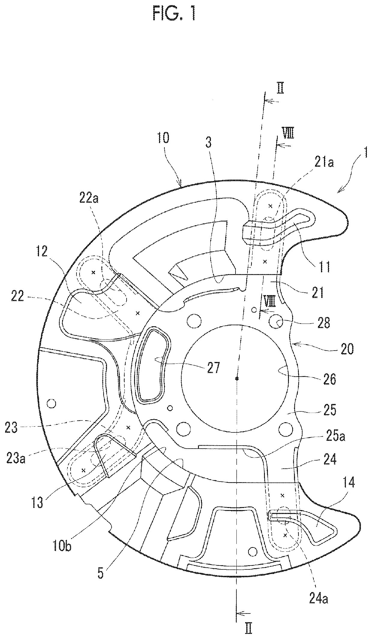
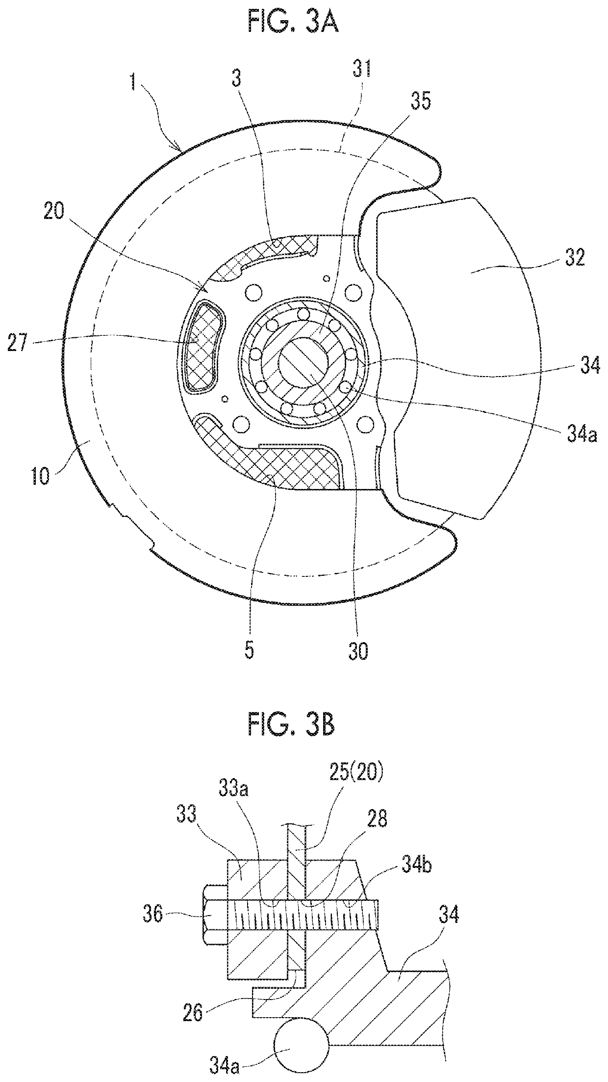
[0040]In this embodiment, a case will be described where the present disclosure is applied to a disc brake device that includes a disc rotor 31 connected to an axle 30, which is rotatably supported by a knuckle 33 that is a non-rotating body through a hub bearing 34 having bearing balls 34a, through a hub 35, and calipers 32 that are disposed so as to interpose both sides of the disc rotor 31 therebetween (refer to FIGS. 3A and 3B). The front views of FIGS. 1, 4, and 6 correspond to diagrams showing a brake dust cover 1, a first plate-like member 10, and a second plate-like member 20, respectively, as viewed from the inner side in a vehicle width direction of a vehicle.

[0041]FIG. 1 is a front view schematically showing the brake dust cover 1 according to this embodiment, and FIG. 2 is a sectional view taken along line II-II of FIG. 1 and viewed in a direction of an arrow....


PUM


Abstract

A brake dust cover is disposed between a non-rotating body rotatably supporting an axle and a disc rotor rotating together with the axle so as to cover the disc rotor from an inner side in a vehicle width direction. The brake dust cover includes a first plate-like member having a C-shape in which a part of a circular ring is cut out, and a second plate-like member coupled to the first plate-like member. The second plate-like member includes a fixed portion fixed to the non-rotating body, and a plurality of support portions extending radially from the fixed portion. The first plate-like member is coupled to the second plate-like member to overlap the support portions such that an opening portion is formed between an inner edge of the first plate-like member and an outer edge of the fixed portion of the second plate-like member when viewed in the vehicle width direction.

Description

INCORPORATION BY REFERENCE[0001]The disclosure of Japanese Patent Application No. 2018-191646 filed on Oct. 10, 2018 including the specification, drawings and abstract is incorporated herein by reference in its entirety.BACKGROUND1. Technical Field[0002]The present disclosure relates to a brake dust cover for a disc brake device that is provided at a wheel of a vehicle.2. Description of Related Art[0003]In the past, it has been widely performed to cover the inside of a disc rotor of a disc brake device with a brake dust cover in order to suppress infiltration of dust or foreign matter from the inner side of a vehicle to the disc rotor.[0004]In this type of brake dust cover, a technique in which an opening portion is provided in the brake dust cover itself and the disc rotor is cooled by air for brake cooling introduced from the outside through the opening portion is known (refer to, for example, Japanese Unexamined Patent Application Publication No. 2018-059572 (JP 2018-059572 A)).S...

Claims


Application Information

Patent Timeline
IPC IPC(8): F16D65/00F16D55/00
CPCF16D2055/0037F16D65/0081F16D55/00F16D65/847
Inventor OGAWA, TAKAHIROFUJIMOTO, TETSUYA
Owner TOYOTA JIDOSHA KK
Learn More