Elongated structure

a technology of elongated structures and elongated shafts, which is applied in the direction of lighting support devices, instruments, and ways, can solve the problems of unattractiveness of known elongated structures, the disadvantages of having a relatively spacious and bulky pedestal compared to the dimensions of the shaft, and the disadvantage of being unattractive, so as to enhance the cooling and heat dissipation of heat generating equipment, and the effect of less vulnerable to vandalism

Active Publication Date: 2020-04-16
SIGNIFY HLDG BV
View PDF0 Cites 9 Cited by
  • Summary
  • Abstract
  • Description
  • Claims
  • Application Information

AI Technical Summary

Benefits of technology

[0018]The elongated structure might have the feature that an outer surface of the wall of the base section is flush with an outer surface of an adjacent wall of an extension section of the tubular body part. This renders the base section to be even more unobtrusive, rendering the elongated structure to be less vulnerable to vandalism and to look more attractive.
[0019]The elongated structure might have the feature that the wall is provided with at least one first vent opening and at least one second vent opening in axial direction on either side of the door. Due to the mutual positions of the first and second vent opening a chimney effect is obtained due to natural convection, this chimney effect enhances cooling and heat dissipation of heat generating equipment. Preferably the first vent opening is provided at the foot of the elongated structure to counteract vandalism by being as unobtrusive as possible. To further enhance the chimney effect (and thus cooling effect), the elongated structure might be provided with an electrically motorized ventilator forcing a cooling fluid, for example air, to flow from the first vent opening to the second vent opening and to counteract backflow.
[0020]The elongated structure might have the feature that the base section has a maximal diameter Db and further sections have a maximal diameter Dp, wherein Dp<=Db<=1.3 * Dp. This renders the advantage that the elongated structure to not stand out from other elongated structures, i.e. from street poles and street light poles in its (direct) environment, and thus not to form a point of interest to vandalism. Furthermore, thus the advantage of a more attractive look of the elongated structure is obtained. These advantages are increased if the elongated structure decreases in diameter from the base section in axial direction, and even further increased when the elongated structure continuously decreases in diameter from the base section in axial direction.

Problems solved by technology

Due to the requirement to fulfill the two functions simultaneously, the known elongated structure has the disadvantages of having a relatively spacious and bulky pedestal compared to the dimensions of the shaft.
This renders the known elongated structure to have the further disadvantages of being unattractive because its pedestal is prominent visible and the pedestal requires relatively a lot of material involving a relatively high bill of material.

Method used


Image

  • Elongated structure
  • Elongated structure
  • Elongated structure

Examples


second embodiment

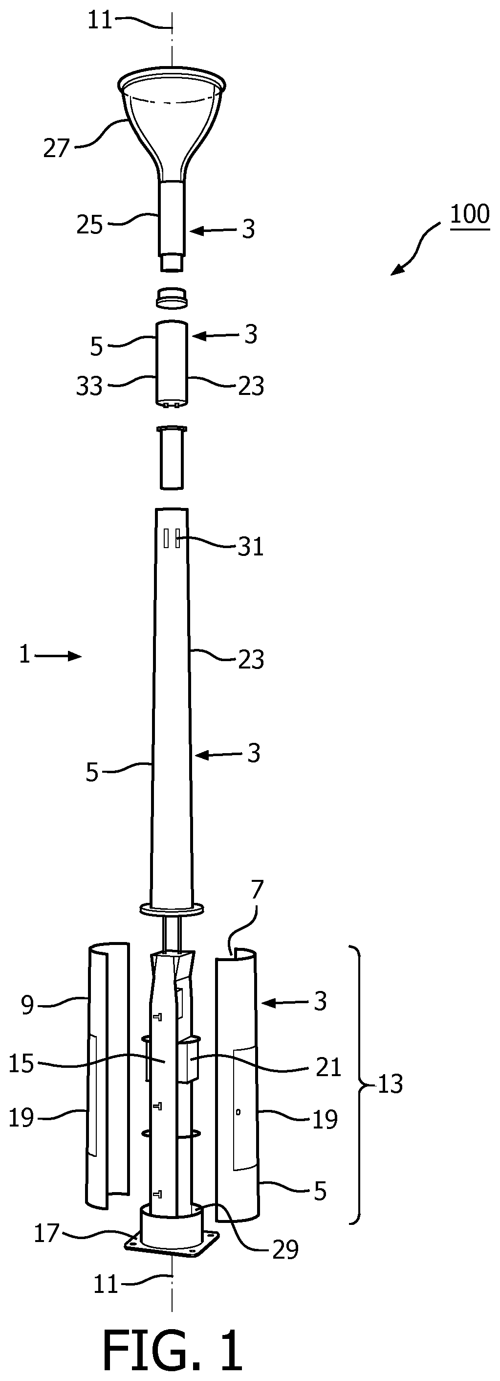
[0035]FIG. 6 shows a schematic overview of an erected, elongated structure 1 comprising a pole 3 having at least a wall 5 around a hollow core as a tubular body part 9 extending along a length axis 11. A base section 13 of the wall of the tubular body part being connected to a foot 17 of the pole and to an extension section 23 along the length axis. As shown, in the elongated structure the diameter Db from the base section continuously decreases in axial direction to the diameter Dp of the extension section and an outer surface 26 of the wall of the base section is flush with an outer surface 28 of an adjacent wall of the extension section of the tubular body part. The outer surface of extension section on its turn is flush with the outer surface 30 of a top section 25. As shown, the diameter of the elongated structure smoothly, gradually decreases from the base section to the top section. The elongated structure is embodied as a modular street pole 100, and further comprises the e...

third embodiment

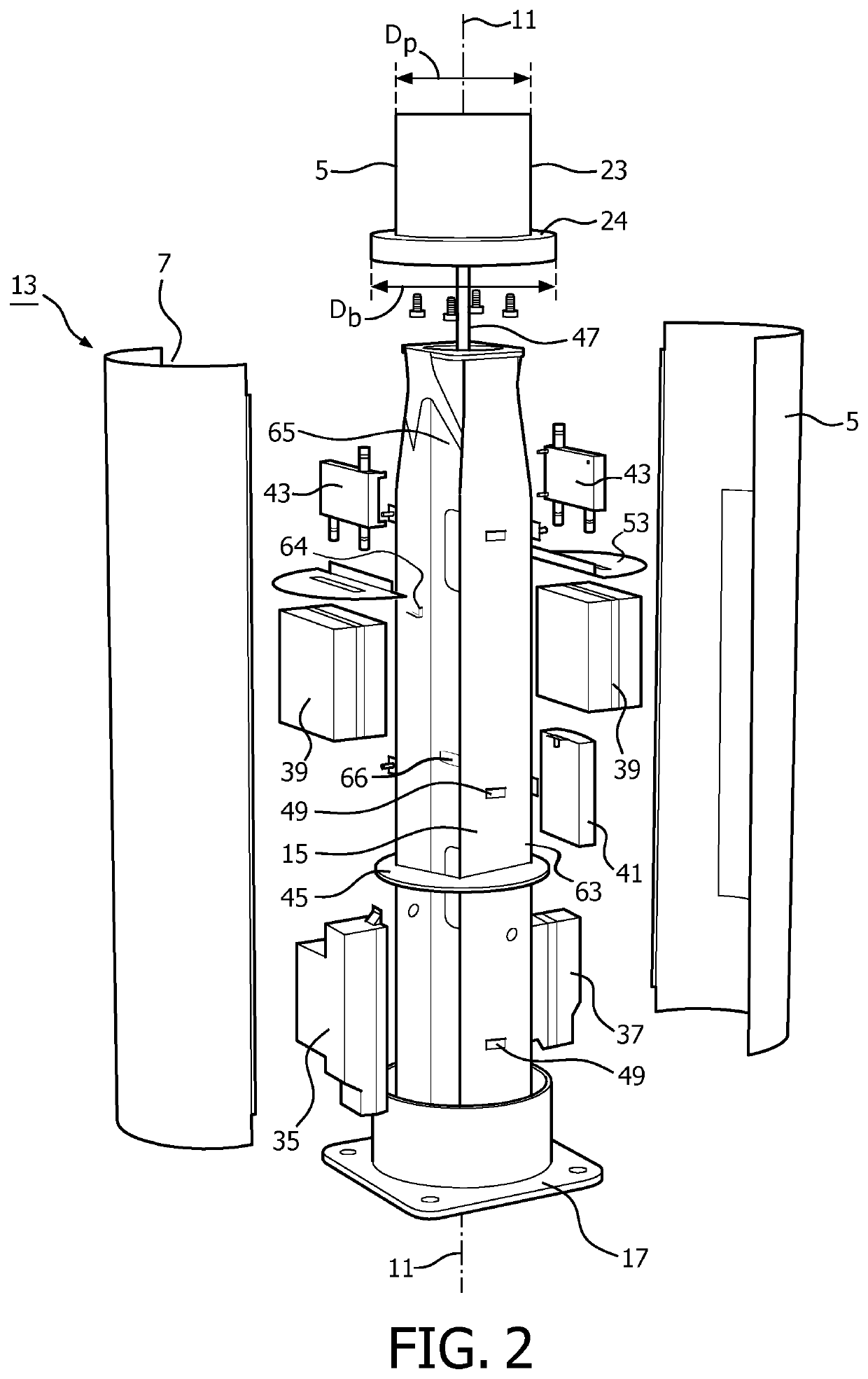
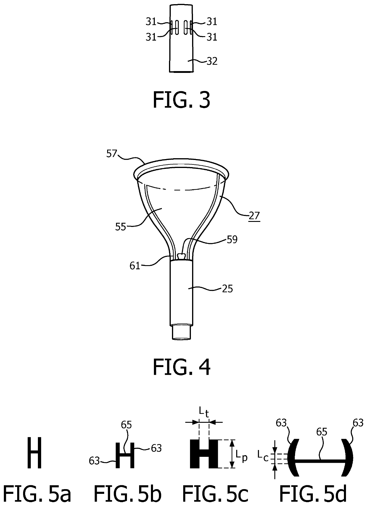
[0036]FIG. 7 shows a schematic view of third embodiment of a base section 13 of an elongated structure 1 according to the invention with doors 19 in open position. The base section has an outer wall 5 which in the base section are practically completely formed by the doors. The doors are in hinged connection to an axially extending H-shaped frame 15 along a longitudinal axis 11 in a cavity or hollow core 7 in the base section (formed when the doors are in closed position) and lie flush with the wall at a foot 17 of the elongated structure. Mounted on the H-shaped frame is a radio 39 which is connected to a converter 35 mounted at an opposite side of the H-shaped frame and in a lower position than the radio.

[0037]It should be noted that the above-mentioned embodiments illustrate rather than limit the invention, and that those skilled in the art will be able to design many alternative embodiments without departing from the scope of the appended claims. In the claims, any reference sig...


PUM


Abstract

The invention provides an elongated structure comprising a pole having a wall around a hollow core as a tubular body part extending along a length axis. A base section of the wall of the tubular body part is connected to an H-shaped frame extending from a foot of the pole along the length axis, said H-shaped frame being arranged in the core. The wall at the location of the H-shaped frame is provided with a door, said door in closed position being flush with the wall and in opened position providing access to the core.

Description

FIELD OF THE INVENTION[0001]The invention relates to an elongated structure having a length axis and comprising a pole comprising a wall around a hollow core as a tubular body part extending along the length axis. The invention further relates to a street pole and a street light pole.BACKGROUND OF THE INVENTION[0002]Such an elongated structure is known from U.S. Pat. No. 6,222,503B1. Said known structure is a street light pole, also referred to as street luminaire, comprising a rectangular, box-shaped pedestal as a base section upon which a shaft is mounted with a lamp housing at its end. The closed, box-shaped pedestal has to simultaneously fulfill two functions, i.e. to support the shaft with mounted lamp housing and to safely accommodate electronics equipment, for example a frequency converter, power supplies, battery backups, and control circuits etc. Due to the requirement to fulfill the two functions simultaneously, the known elongated structure has the disadvantages of having...

Claims


Application Information

Patent Timeline
Patent Type & Authority Applications(United States)
IPC IPC(8): F21S8/08F21V21/10
CPCE04H12/085F21V21/10F21S8/085F21W2131/103F21W2111/02F21V25/00E04H12/003E04H12/08F21V7/0008G08G1/095
Inventor BEMBRIDGE, MATHEW LEEFRIEDERICHS, WINAND HENDRIK ANNA MARIABIJL, PETRADE GOEDEREN-OEI, AY LING
Owner SIGNIFY HLDG BV
Why Eureka
Try Eureka