
Optical film

a technology of optical film and film film, applied in the field of optical film, can solve problems such as brightness degradation

Active Publication Date: 2020-04-16
LMS
View PDF3 Cites 2 Cited by
  • Summary
  • Abstract
  • Description
  • Claims
  • Application Information

AI Technical Summary

Benefits of technology

The patent text discusses the use of a laminated optical film in a display. The film is made stronger throughout to improve reliability, but this can result in decreased brightness. The technical problem to be solved is to find a way to increase the brightness of the film while minimizing its deformation when laminated with other sheets. Additionally, the film should provide an air gap for better light diffusing and maintain its strength while minimizing brightness deterioration when laminated with a diffuser sheet and prism sheet.

Problems solved by technology

A simple laminated optical film may have improved reliability due to the increased strength throughout the optical film but its brightness may be deteriorated.

Method used


Image

  • Optical film
  • Optical film
  • Optical film

Examples


Embodiment Construction

[0024]The present disclosure will be described in detail with reference to the accompanying drawings. The same elements in the drawings have the same reference numerals and thus the cumulative explanation will be omitted for simplicity. And the described terms are defined by considering the function in the present disclosure, which may be varied according to the user's intention or convention. Therefore, the definition of the terms used should be interpreted on the basis of the content throughout this description and corresponding functions.

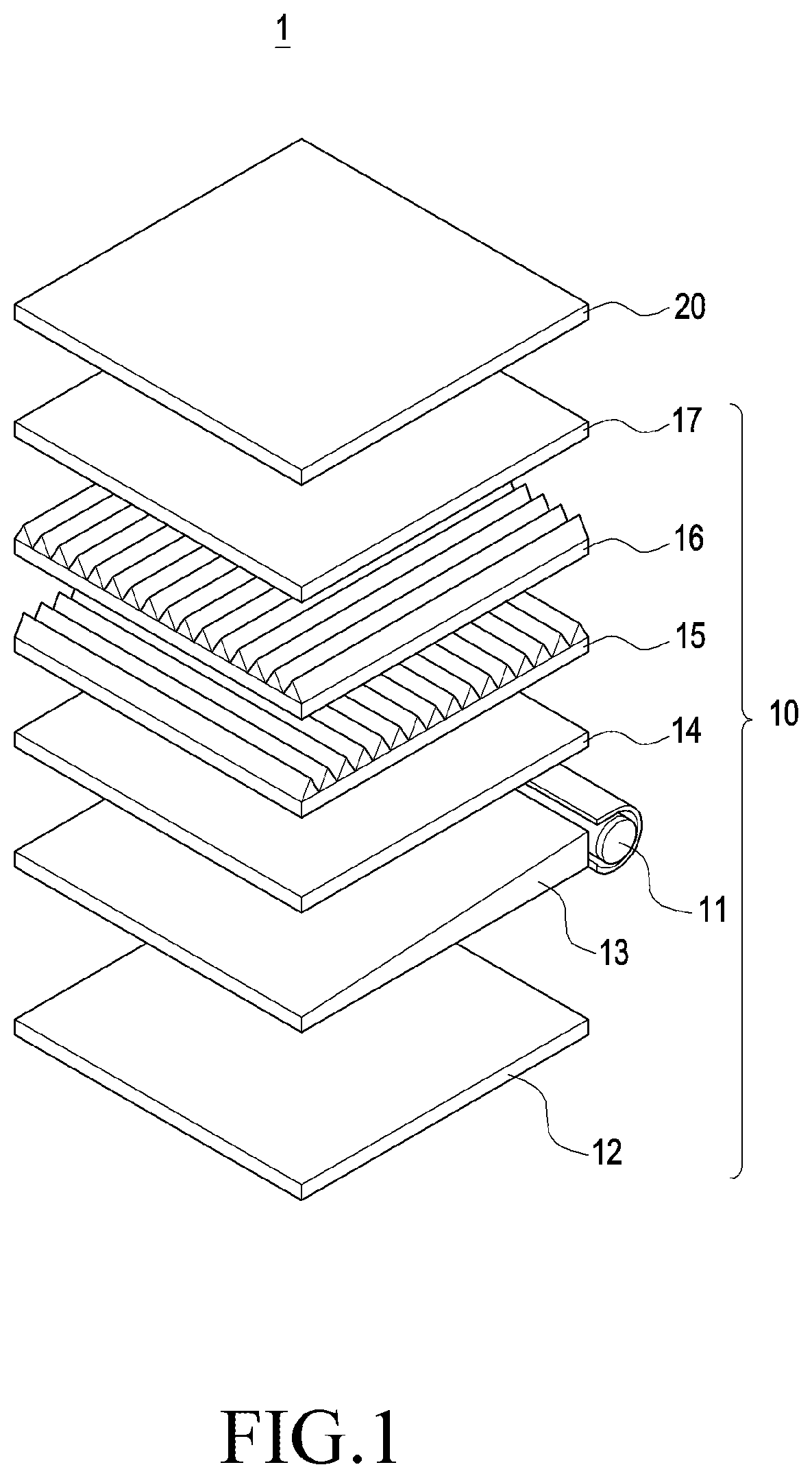
[0025]FIG. 1 is a perspective view showing each component for a liquid crystal display module in accordance with one of preferred aspects of the present disclosure. Referring to FIG. 1, a liquid crystal display (LCD) module (1) includes a backlight unit (10) and a liquid crystal display (LCD) panel (20). In general, a backlight unit (10) is located to the backside of the liquid crystal display panel (20) to emit a light through the liquid crystal...


PUM

PropertyMeasurementUnit
heightaaaaaaaaaa
opticalaaaaaaaaaa
diameteraaaaaaaaaa

Abstract

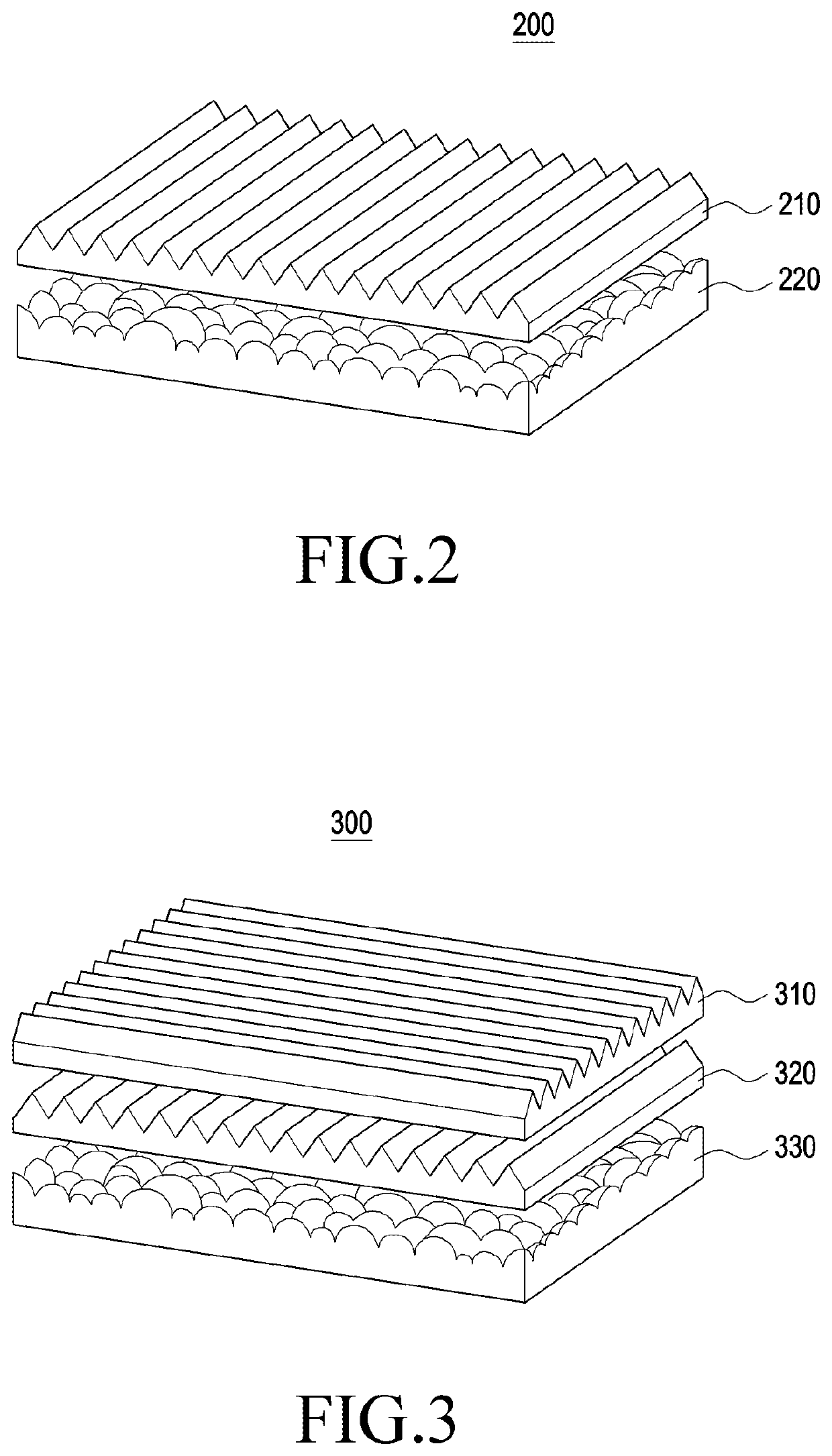
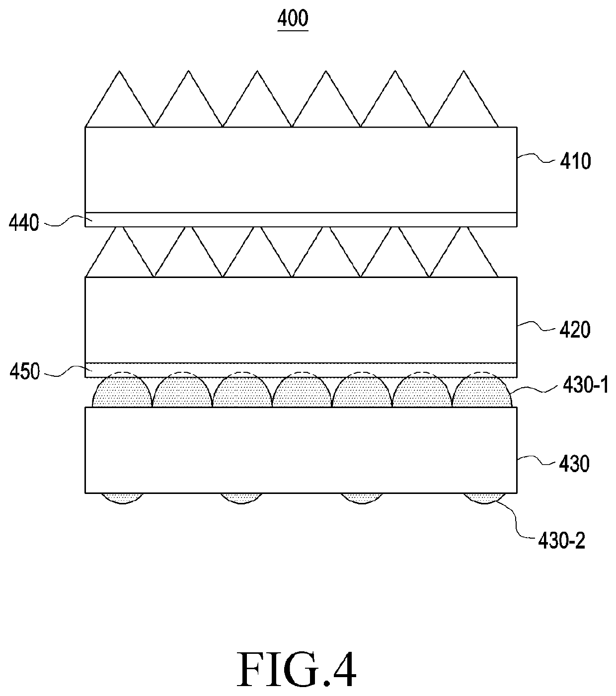
Disclosed is an optical film includes a first prism sheet including a plurality of first prisms arranged on one side of the first prism sheet, a second prism sheet including a plurality of second prisms arranged on one side of the second prism sheet, and a diffuser sheet including a plurality of first protrusions and a plurality of second protrusions arranged on one side of the diffuser sheet. The optical film is prepared to have a height of the first protrusions being greater than a height of the second protrusions. The optical film is further prepared that the first prism sheet, the second prism sheet and the diffuser sheet laminated where the first protrusions of the diffuser sheet is adhered to a side of the first prism sheet where no first prisms are arranged, and the first prisms of the first prism sheet are adhered to a side of the second prism sheet where no second prisms are arranged.

Description

CROSS REFERENCE TO RELATED APPLICATION[0001]This application claims priority under 35 U.S.C. 119 to Korean Patent Application No. 10-2018-0122651, filed on Oct. 15, 2018, which is hereby incorporated by reference in its entirety.BACKGROUNDTechnical Field[0002]The present disclosure relates to an optical film utilized for LCD modules and further relates to an optical film which can diffuse light emitted from a light source assembled in a light guide plate module.Description of Related Art[0003]In general, an LCD (liquid crystal display) module includes a backlight module which distributes light throughout the screen. A backlight module includes a lamp, a reflector reflecting the light emitted from a lamp and a light guided plate (LGP) distributing the light throughout the display area.[0004]On the top of the light guided plate (LGP), an optical film including a diffuser sheet which uniformly diffuses the light and a prism sheet which condenses the diffused light is placed. An optical...

Claims


Application Information

Patent Timeline
Patent Type & Authority Applications(United States)
IPC IPC(8): F21V8/00G02B5/02
CPCG02B6/0051G02B5/0221G02B6/0053G02B5/0278G02F1/133606G02F1/133615G02F1/133607G02B5/045B32B3/14B32B27/36G02B5/04G02B5/0268B29D11/0073G02F1/133504B32B2457/202B32B2307/40
Inventor LEE, DONGCHEOLCHOI, JINYEONOH, SEJINLEE, WOOJONGKIM, MINHOKIM, DUYI
Owner LMS
Learn More