
Brake Fluid Detection System

a technology of brake fluid and detection system, which is applied in the direction of braking system, force/torque/work measurement apparatus, instruments, etc., can solve the problems of affecting brake performance, braking force required, and brake fluid starting to absorb moisture, so as to reduce the cost of data storage and facilitate operation.

Inactive Publication Date: 2020-04-23
PEACEFUL THRIVING ENTERPRISE
View PDF0 Cites 0 Cited by
  • Summary
  • Abstract
  • Description
  • Claims
  • Application Information

AI Technical Summary

Benefits of technology

The present invention is a brake fluid detection system that uses a portable detection device in combination with a cloud database and a portable internet device. This allows users to access brake fluid-related data in real-time. The system has significantly reduced data storage costs due to advanced cloud computing and communication technology. The detected data is processed on the clouds and then transmitted to a portable internet device, where operations are performed and the detection data is displayed. This system provides a more-precise and massive database with portability and easy operation.

Problems solved by technology

The brake cylinders receive the brake fluid and push the brake pads against the brake discs, resulting in the braking force required.
However, the brake fluid starts to absorb moisture since it is filled into the brake system.
Thus the brake performance will be affected if the brake fluid is not replaced periodically and cause dangerous situations on the rod.
The moisture in the brake fluid can lower the boiling point of the brake fluid, resulting in insufficient braking pressure and reduced braking effect.
When the brake system works, heat generated by the friction between brake pads and the brake discs causes the temperature of the system to rise.
A certain amount of air entering the brake pipeline will cause inadequate brake force because the air is compressible and the brake failure may occur if the case is serious.
Yet the cost and the volume of the device are increased along with the database expansion.
Another issue to be considered is that certain users may not understand how to update the database.
It is obvious that the testing device is unable to be moved freely for detecting objects to be tested.
The objects can only be detected within a certain range due to the limited length of the solid wire.

Method used


Image

  • Brake Fluid Detection System
  • Brake Fluid Detection System

Examples


Embodiment Construction

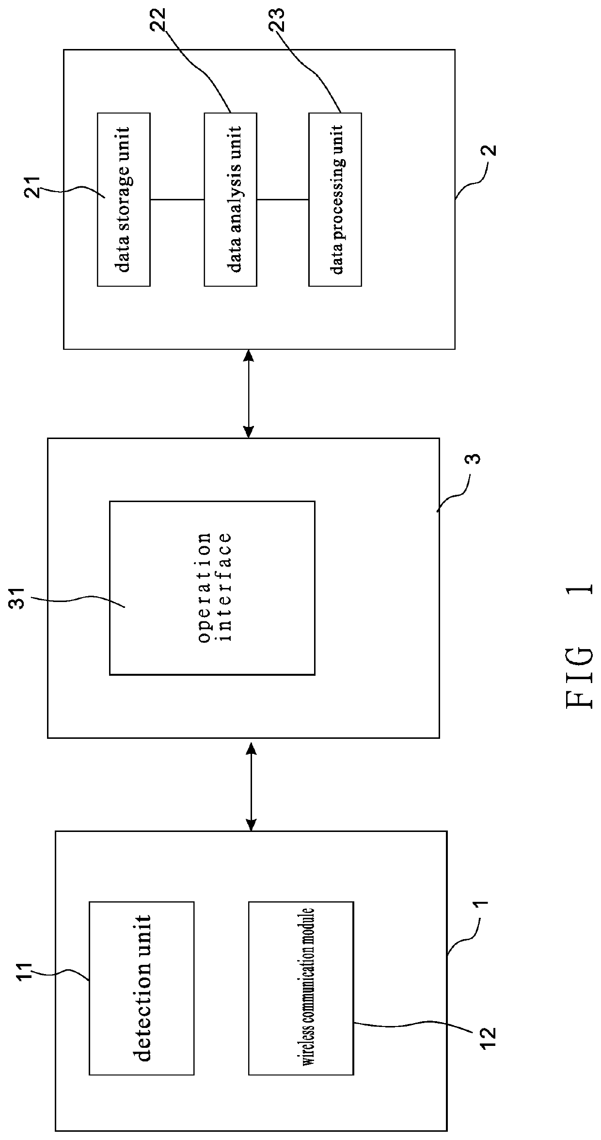
[0018]As shown in FIG. 1, a brake fluid detection system according to the present invention includes a first device 1, a second device 2 and a third device 3. The first device 1 consists of a detection unit 11 and a data transmission unit connected to each other. The data transmission unit is provided with a wireless communication module 12 which is used to provide a wireless connection for sending and receiving data. The detection unit 11 is a probe arranged with a sensing circuit and in direct contact with a brake fluid to be detected for sensing changes in water content or temperature of the brake fluid.

[0019]The second device 2 is a cloud database composed of a data storage unit 21, a data analysis unit 22, and a data processing unit 23.

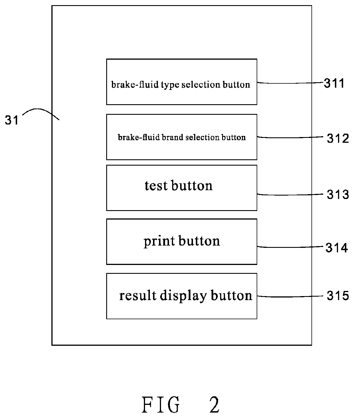
[0020]The third device 3 is a portable internet device (such as a cell phone or a tablet) provided with an application software which is used for receiving and displaying data of the brake fluid after detection and having an operation interface 3...


PUM

PropertyMeasurementUnit
temperatureaaaaaaaaaa
stepping forceaaaaaaaaaa
pressureaaaaaaaaaa

Abstract

A brake fluid detection system used for detecting the brake fluid quality of a brake device is revealed. The detection system includes a first device having a detection unit connected to a data transmission unit, a second device composed of a data storage unit, a data analysis unit, and a data processing unit, and a third device provided with an application software. The data transmission unit is provided with a wireless communication module. The third device is a portable internet device. The third device receives detected data obtained and uploaded by the first device and users set the detected data by operating the application software. Then the original detected data and the detected data set by users is sent to the data processing unit of the second device through a wireless network for data processing to get detection data. Lastly detection data is displayed on the third device.

Description

CROSS REFERENCE OF RELATED APPLICATION[0001]This is a Continuation-In-Part application that claims the benefit of priority under 35 U.S.C. § 120 to a non-provisional application, application Ser. No. 15 / 686,141, filed Aug. 24, 2017.NOTICE OF COPYRIGHT[0002]A portion of the disclosure of this patent document contains material which is subject to copyright protection. The copyright owner has no objection to any reproduction by anyone of the patent disclosure, as it appears in the United States Patent and Trademark Office patent files or records, but otherwise reserves all copyright rights whatsoever.BACKGROUND OF THE PRESENT INVENTIONField of Invention[0003]The present invention relates to a brake fluid detection system, and more particularly to a brake fluid detection system that uses mobile internet devices, such as tablets or cell phones, to detect quality data of the brake fluid detected, to connect to the cloud database for data processing and analysis, and to display the detecti...

Claims


Application Information

Patent Timeline
Patent Type & Authority Applications(United States)
IPC IPC(8): G01L5/22B60T17/22B60T8/88
CPCG01L5/225F16D66/021B60T17/22B60T8/885B60T17/221
Inventor CHIEN, SHIH-HSIANG
Owner PEACEFUL THRIVING ENTERPRISE
Learn More