Device and method for load distribution of base station in wireless communication system

a wireless communication system and wireless communication technology, applied in the direction of electrical equipment, network traffic/resource management, connection management, etc., can solve the problems of limited radio resources and backhaul network capacity provided by one base station, and the service quality experienced by the terminals in the base station cell may be deteriorated, so as to achieve efficient load distribution and control cell load

Active Publication Date: 2020-04-30
SAMSUNG ELECTRONICS CO LTD
View PDF0 Cites 5 Cited by
  • Summary
  • Abstract
  • Description
  • Claims
  • Application Information

AI Technical Summary

Benefits of technology

[0021]An apparatus and a method according to various embodiments of the present disclosure may, if a cell is over-loaded in a base station, address the over-load of the cell by redistributing an idle terminal and more efficiently control the cell load. In addition, with respect to a terminal to be released due to no traffic for a specific time, the cell load may be distributed and the over-load may be prevented in advance, by prompting the camping on a low-loaded frequency or cell if the connection is released. Further, using a method suggested in the present disclosure, real-time load information may be updated rapidly, and efficient load distribution is achieved without having to broadcasting the load information for unnecessary neighboring cells.
[0022]Effects obtainable from the present disclosure are not limited to the above mentioned effects, and other effects which are not mentioned may be clearly understood by those skilled in the technical field to which the present disclosure belongs through the following descriptions.

Problems solved by technology

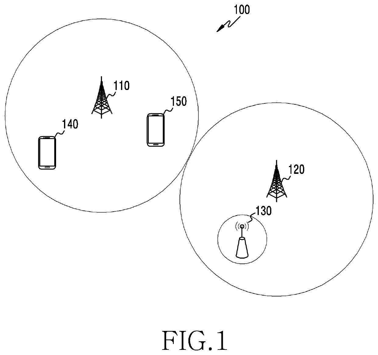
Radio resources and a backhaul network capacity provided by one base station are limited.
Thus, if a great number of terminals access the base station at a specific time, traffic exceeding the backhaul network capacity in amount as well as the radio channel of the base station may occur, and a service quality experienced by the terminals in the base station cell may be deteriorated.

Method used


Image

  • Device and method for load distribution of base station in wireless communication system
  • Device and method for load distribution of base station in wireless communication system
  • Device and method for load distribution of base station in wireless communication system

Examples


Embodiment Construction

[0036]The terms used in the present disclosure are only used to describe specific embodiments, and are not intended to limit other embodiments. Singular expressions may include plural expressions as well unless the context clearly indicates otherwise. All terms used herein including technical and scientific terms may have the same meaning as those commonly understood by a person skilled in the art to which the present disclosure pertains. Terms such as those defined in a generally used dictionary among the terms used in the present disclosure may be interpreted to have the meanings equal or similar to the contextual meanings in the relevant field of art, and are not to be interpreted to have ideal or excessively formal meanings unless clearly defined in the present disclosure. In some cases, even a term defined in the present disclosure should not be interpreted to exclude embodiments of the present disclosure.

[0037]In various embodiments of the present disclosure to be described be...


PUM


Abstract

The present disclosure relates to a 5th generation (5G) or pre-5G communication system for supporting a higher data transfer rate beyond a 4th generation (4G) communication system, such as long term evolution (LTE). An operation method of a reception device in a wireless communication system comprises the steps of: receiving a signal transmitted through a plurality of antennas of a transmission device; determining an initial symbol vector on the basis of the signal; determining a first candidate symbol vector, on the basis of a plurality of solution vectors obtained by searching for the initial symbol vector; determining a second candidate symbol vector by changing at least one symbol value of the first candidate symbol vector; and determining a symbol vector transmitted from the transmission device, on the basis of at least a part of the second candidate symbol vector.

Description

TECHNICAL FIELD[0001]The present disclosure generally relates to a method for base station load distribution in a wireless communication system, and more particularly, to an apparatus and a method for redistributing an idle terminal of an over-loaded base station based on base station load, and prompting terminal camping to a low-loaded base station in the wireless communication system.BACKGROUND ART[0002]To meet the demand for wireless data traffic having increased since deployment of 4th generation (4G) communication systems, efforts have been made to develop an improved 5th generation (5G) or pre-5G communication system. Therefore, the 5G or pre-5G communication system is also called a ‘Beyond 4G Network’ or a ‘Post Long Term Evolution (LTE) System’.[0003]The 5G communication system is considered to be implemented in higher frequency (mm Wave) bands, e.g., 60 GHz bands, so as to accomplish higher data rates. To decrease propagation loss of the radio waves and increase the transmi...

Claims


Application Information

Patent Timeline
Patent Type & Authority Applications(United States)
IPC IPC(8): H04W28/08H04W24/10H04W88/08H04W28/12H04W76/27H04W16/10H04W28/02H04W28/20H04W72/10
CPCH04W16/10H04W28/0289H04W88/08H04W28/085H04W76/27H04W72/10H04W28/12H04W28/0284H04W28/20H04W24/10H04W28/02H04W28/0942H04W16/32H04W72/56H04W28/082
Inventor CHOI, JUNGMINKIM, HANSEOK
Owner SAMSUNG ELECTRONICS CO LTD
Why Eureka
Try Eureka