Antenna device for biological measurement, pulse wave measuring device, blood pressure measuring device, apparatus, biological information measuring method, pulse wave measuring method, and blood pressure measuring method

a biological and measuring device technology, applied in the direction of diagnostic recording/measuring, transmission monitoring, angiography, etc., can solve the problems of inability to accurately measure the pulse wave as biological information, the received signal level varies, and the inability to disclose or suggest the position displacement, etc., to achieve accurate measurement of biological information

Inactive Publication Date: 2020-05-07
ORMON CORP +1
View PDF0 Cites 8 Cited by
  • Summary
  • Abstract
  • Description
  • Claims
  • Application Information

AI Technical Summary

Benefits of technology

[0006]Accordingly, an object of the present invention is to provide an antenna device for biological measurement capable of accurately measuring biological information from a measurement target site even when a position displacement of the transmission/reception antenna group occurs with respect to the measurement target site. Another object of the present invention is to provide a pulse wave measuring device, a blood pressure measuring device, and an apparatus provided with the antenna device for bio

Problems solved by technology

However, Patent Document 1 does not disclose or suggest how a position displacement is to be handled and measured when a position displacement of the transmission/reception antenna pair occurs with respect to the measurement target site.
Without any countermeasure, for example, th

Method used


Image

  • Antenna device for biological measurement, pulse wave measuring device, blood pressure measuring device, apparatus, biological information measuring method, pulse wave measuring method, and blood pressure measuring method
  • Antenna device for biological measurement, pulse wave measuring device, blood pressure measuring device, apparatus, biological information measuring method, pulse wave measuring method, and blood pressure measuring method
  • Antenna device for biological measurement, pulse wave measuring device, blood pressure measuring device, apparatus, biological information measuring method, pulse wave measuring method, and blood pressure measuring method

Examples


Embodiment Construction

[0142]Hereinafter, an embodiment of the present invention will be described in detail with reference to the drawings.

(Configuration of Sphygmomanometer)

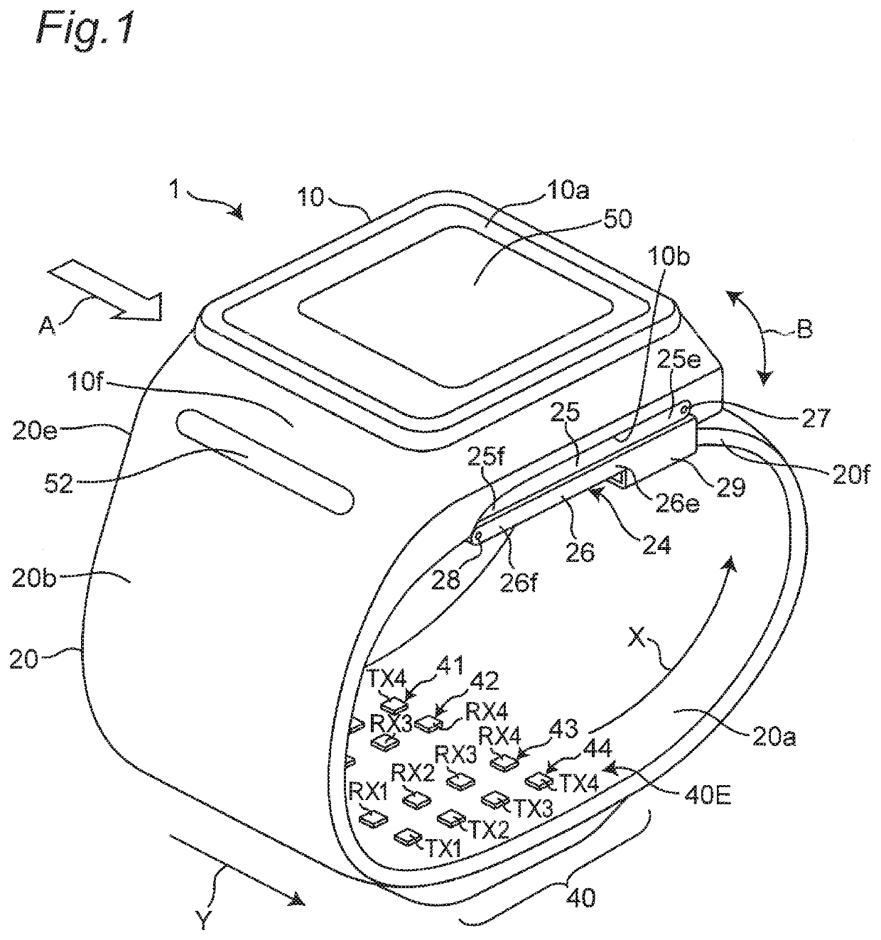
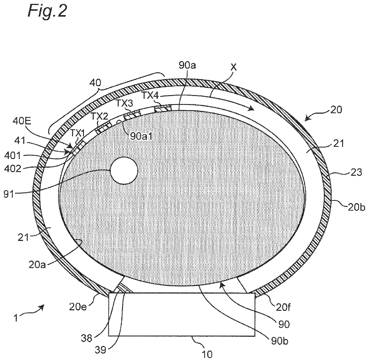
[0143]FIG. 1 illustrates a perspective view of an appearance of a wrist sphygmomanometer (the whole body is indicated by reference numeral 1) according to an embodiment of an antenna device for biological measurement, a pulse wave measuring device, and a blood pressure measuring device of the present invention. FIG. 2 schematically illustrates a cross section perpendicular to a longitudinal direction of a left wrist 90 in a state where the sphygmomanometer 1 is worn on the left wrist 90 as a measurement target site (hereinafter, referred to as “wearing state”).

[0144]As illustrated in the drawings, the sphygmomanometer 1 roughly includes a belt 20 to be worn so as to surround the user's left wrist 90 and a main body 10 integrally fitted to the belt 20. This sphygmomanometer 1 is configured as a whole corresponding to a blood pressure ...


PUM


Abstract

An antenna device for biological measurement according to the present invention includes a belt to be worn as surrounding a measurement target site of a living body. A transmission/reception antenna group is provided to the belt and includes a plurality of antenna elements. In a wearing state where the belt is worn as surrounding an outer surface of the measurement target site, a radio wave is emitted toward the measurement target site using any one of the antenna elements as a transmission antenna. A reflected radio wave is received using any one of the antenna elements as a reception antenna. A transmission/reception antenna pair formed of the transmission antenna and the reception antenna is selected by switching or weighted among the plurality of antenna elements based on a reception output.

Description

CROSS-REFERENCE TO RELATED APPLICATION[0001]This is a continuation application of International Application No. PCT / JP2018 / 024034, with an International filing date of Jun. 25, 2018, which claims priority of Japanese Patent Application No. 2017-142221 filed on Jul. 21, 2017, the entire content of which is hereby incorporated by reference.TECHNICAL FIELD[0002]The present invention relates to an antenna device for biological measurement, and more particularly to an antenna device for biological measurement that emits radio waves toward a measurement target site of a living body or receives radio waves from the measurement target site to measure biological information. The present invention also relates to a pulse wave measuring device, a blood pressure measuring device, and an apparatus provided with such an antenna device for biological measurement. The present invention also relates to a biological information measuring method for emitting radio waves toward a measurement target sit...

Claims


Application Information

Patent Timeline
IPC IPC(8): A61B5/021H01Q1/27H04B1/3827H04B17/336A61B5/00A61B5/022
CPCH04B1/385H01Q1/273A61B5/6802A61B5/02125H04B2001/3855A61B5/0507A61B5/02225H04B17/336A61B5/022A61B5/681A61B5/0022A61B5/1495H04B2001/3861
Inventor OZAWA, HISASHISAITO, KEISUKEKAMADA, KEIGOKAWABATA, YASUHIRO
Owner ORMON CORP
Why Eureka
Try Eureka