
Accelerator control method and device, power system and unmanned aerial vehicle

a technology of accelerator control and control method, which is applied in the direction of sustainable transportation, transportation and packaging, and efficient propulsion technologies, etc., can solve the problems of failure to meet the requirements of control accuracy, poor accuracy, and control of the accelerator of the esc on a device such as an unmanned aerial vehicle, so as to shorten the accelerator control cycle and avoid data inaccuracy. , the effect of increasing the baud ra

Active Publication Date: 2020-05-07
SHENZHEN AUTEL INTELLIGENT AVIATION TECH CO LTD
View PDF0 Cites 2 Cited by
  • Summary
  • Abstract
  • Description
  • Claims
  • Application Information

AI Technical Summary

Benefits of technology

The patent describes a method and device for controlling the acceleration of a vehicle's motor. The device uses a network of sensors to detect the driver's intent to accelerate and sends a signal to the motor to accelerate quickly. The signal is sent using a digital network, which ensures accurate and reliable data transmission. This allows for faster and more accurate control of the motor, resulting in a smoother and more efficient vehicle.

Problems solved by technology

The existing method for controlling the accelerator of the ESC on a device such as an unmanned aerial vehicle (UAV) has disadvantages of a long control cycle, poor accuracy and a failure to meet higher requirements for control accuracy.

Method used


Image

  • Accelerator control method and device, power system and unmanned aerial vehicle
  • Accelerator control method and device, power system and unmanned aerial vehicle

Examples


Embodiment Construction

[0045]For ease of understanding this application, this application is described more fully below with reference to the related accompanying drawings. The accompanying drawings show preferred embodiments of this application. However, this application can be implemented in various different forms, and is not limited to the embodiments described in this specification. Conversely, the embodiments are described for the purpose of providing a more thorough and comprehensive understanding of the content disclosed in this application.

[0046]It should be noted that an element described as being “fixed” to another element may be directly on the other element, or an intervening components may be present. When an element is considered as being “connected” to another element, the element may be directly connected to the another element or indirectly connected to the another element. The terms “vertical”, “horizontal”, “left”, “right” and similar expressions used herein are only used for the purpo...


PUM


Abstract

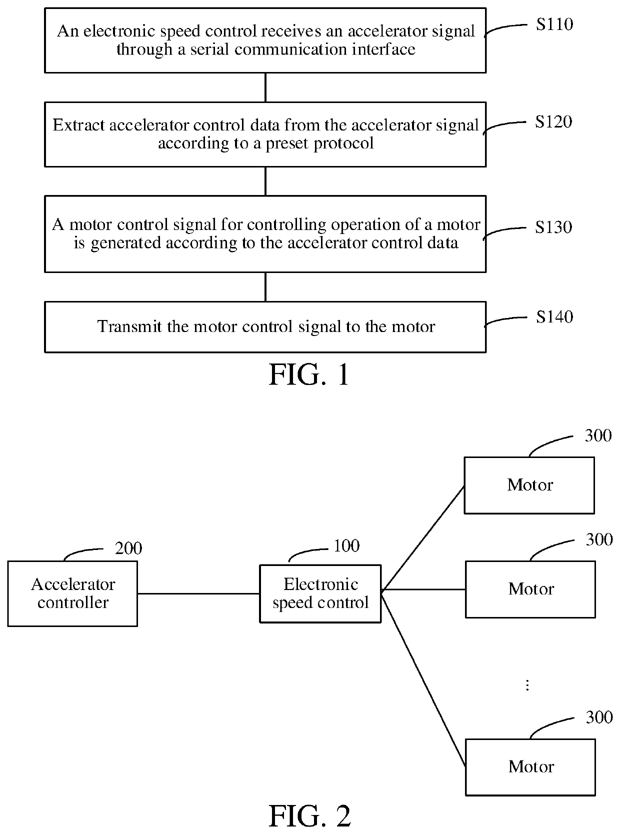
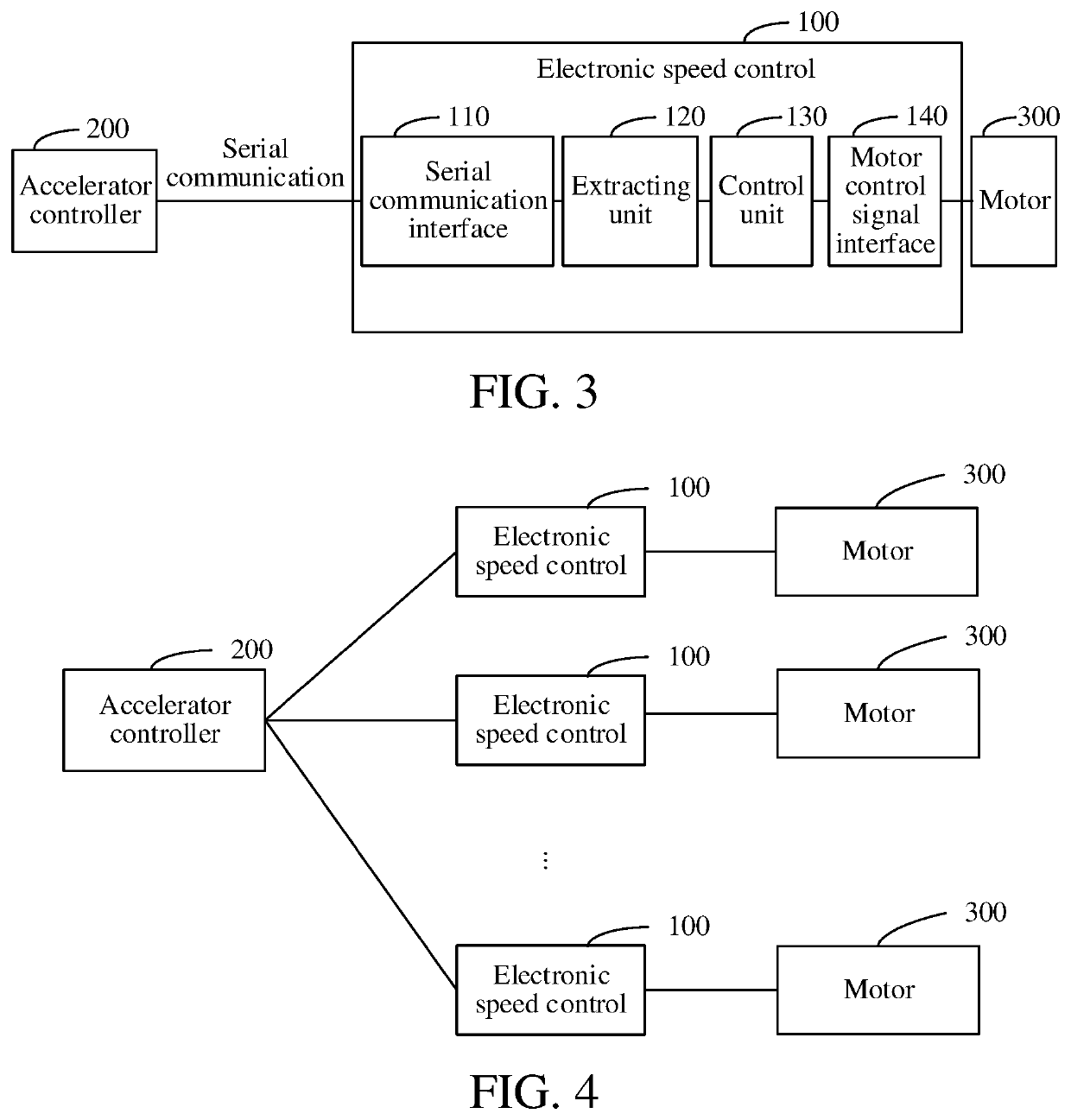
The present application relates to an accelerator control method and device, a power system and an unmanned aerial vehicle (UAV). The method includes: receiving, by an electronic speed control (ESC), an accelerator signal through a serial communication interface; extracting accelerator control data from the accelerator signal; generating, according to the accelerator control data, a motor control signal for controlling operation of a motor; and transmitting the motor control signal to the motor. The accelerator signal received through the serial communication interface is a digital signal subjected to small interference during transmission, unlike an analog signal that is susceptible to interference such as impedance and capacitive reactance, which causes data inaccuracy. In addition, in the manner of serial communication, a higher baud rate may be adopted to shorten an accelerator control cycle, thereby achieving high-speed control of an accelerator and increasing the control frequency.

Description

[0001]This application is a continuation of International Patent Application No. PCT / CN2017 / 096662 filed on Aug. 9, 2017, which claims priority to Chinese Patent Application No. 201710497398.8 filed on Jun. 26, 2017, both of which are incorporated by reference herein in their entireties.BACKGROUNDTechnical Field[0002]The present application relates to the field of accelerator control, and in particular, to an accelerator control method and device, a power system and an unmanned aerial vehicle (UAV).Related Art[0003]With the development of technology and the continuous improvement of people's requirements for product performance, upper-level control of increasingly more products is forced to require higher control frequencies, shorter control cycles and even precise control.[0004]When a user operates a remote control, an operation signal is sent to a flight control module. Then the flight control module obtains an accelerator signal of each electronic speed control (ESC) through calc...

Claims


Application Information

Patent Timeline
IPC IPC(8): B60L15/20B64C39/02
CPCB64C2201/146B64C2201/027B64C2201/162B60L2200/10B64C2201/042B64C2201/108B64C39/024B60L15/20B64D31/00B64U50/19B64U2201/20B64U10/14Y02T10/72B64D27/24B64D31/06Y02T50/60B64U2201/00B64U10/13B64U30/20B64U50/14
Inventor YAN, SHIZHI
Owner SHENZHEN AUTEL INTELLIGENT AVIATION TECH CO LTD
Learn More