Combustion device and infrared reflective plate

a technology of infrared reflection and combustion device, which is applied in the direction of combustion type, mirror, burner, etc., can solve the problems of limited efficiency of infrared ray conversion efficiency of heated ceramic plate, object not being heated uniformly, overheating on food surface, etc., and achieves more uniform heating and more uniform infrared rays. , the effect of generating stronger and more uniform infrared rays

Inactive Publication Date: 2020-05-07
GRAND MATE
View PDF48 Cites 0 Cited by
  • Summary
  • Abstract
  • Description
  • Claims
  • Application Information

AI Technical Summary

Benefits of technology

[0009]The advantage of the present invention is to achieve more uniformly heating on an infrared ray generation mesh with a reflective structure of an infrared reflective plate, and to keep the high temperature of the infrared ray generation mesh such that the combustion device is favorable to generate stronger and more uniform infrared rays.
is to achieve more uniformly heating on an infrared ray generation mesh with a reflective structure of an infrared reflective plate, and to keep the high temperature of the infrared ray generation mesh such that the combustion device is favorable to generate stronger and more uniform infrared rays.

Problems solved by technology

However, heat is conducted from the surface of the object to the inside thereof, resulting in the object not being heated uniformly.
It often brings about overheating on food surface but being undercooked in the interior.
However, the efficiency of the heated ceramic plate converting into infrared rays is limited, and the open fire is too small to heat the surface of the food to golden brown.

Method used


Image

  • Combustion device and infrared reflective plate
  • Combustion device and infrared reflective plate
  • Combustion device and infrared reflective plate

Examples


first embodiment

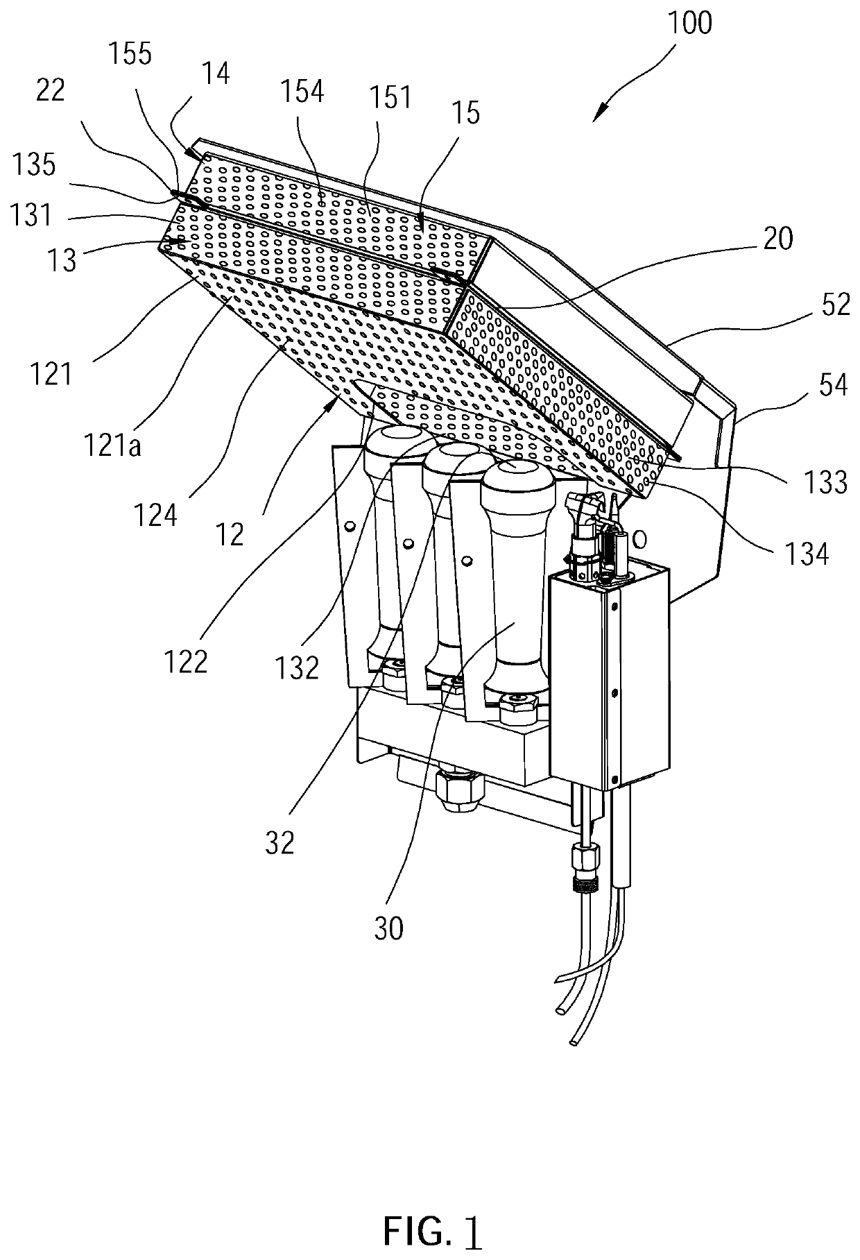
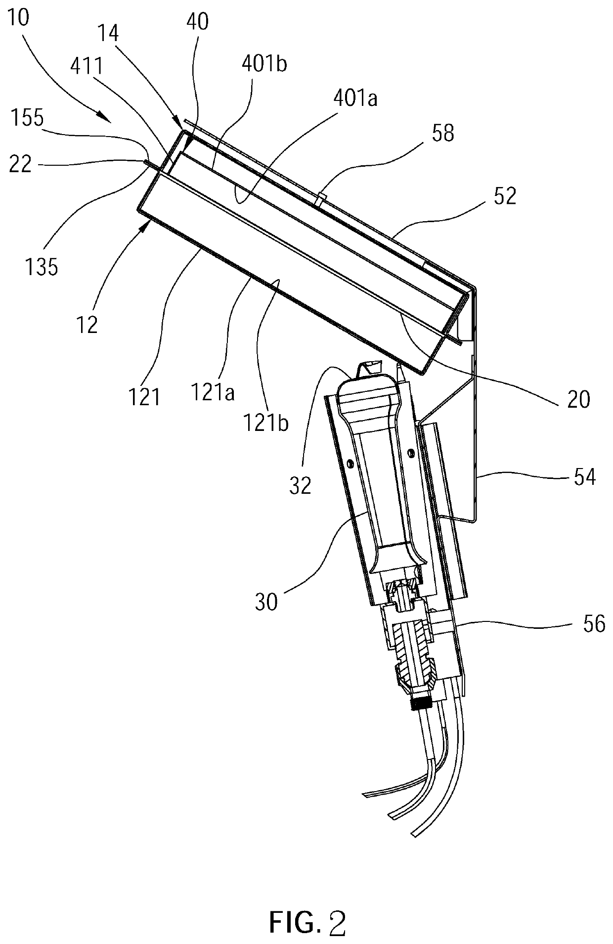
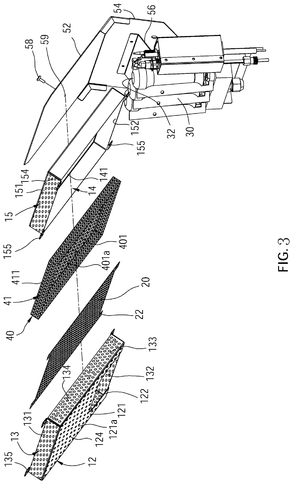
[0023]As illustrated in FIG. 1 to FIG. 7, a combustion device 100 of the first embodiment according to the present invention includes a supporting assembly 10, an infrared ray generation device exemplified by an infrared ray generation mesh 20, an infrared reflective plate 40 and at least one burner 30.

[0024]As illustrated in FIG. 3, the supporting assembly 10 comprises a tilted metallic front cover 12 and a rear cover 14. Wherein, the front cover 12 has a flat rectangular cover plate 121 including a plurality of holes 124 passing between an exterior surface and an interior surface thereof. The tilted front cover 12 further comprises a surrounding wall 13 which has an upper side wall 131 connected to a top edge of the cover plate 121, a lower side wall 132 connected to a bottom edge of the cover plate 121, and two side walls 133 connected to corresponding two side edges of the cover plate 121. All the upper side wall 131, the lower side wall 132 and two side walls 133 have a plurali...

fourth embodiment

[0037]In addition, an infrared reflective plate 90 of the combustion device of the fourth embodiment according to the present invention is shown in FIG. 11. In practice, each of the convex parts 921 on the reflective structure 92 of the infrared reflective plate 90 is a strap in shape and forms a parallel arrangement with each other. A long axis of the convex parts 921 and a long axis of the embossings 922 extend along a predetermined direction from one end 90a of the infrared reflective plate 90 toward corresponding one end 90b.

[0038]With the above reflective structures of the infrared reflective plates, the flames are favorable to more uniformly heat the infrared ray generation mesh 20 and the front cover 12, keep the high temperature of the infrared ray generation mesh 20, and help the combustion device generate stronger and more uniform infrared rays.

[0039]In addition, when infrared rays scatter from the holes 124 of the front cover 12 and from the front cover 12 itself, the in...


PUM

PropertyMeasurementUnit
densityaaaaaaaaaa
areaaaaaaaaaaa
thermal energyaaaaaaaaaa

Abstract

A combustion device includes at least one burner, an infrared reflective plate, and an infrared ray generation mesh. The at least one burner includes a flame outlet; the supporting assembly includes a cover plate which has an opening corresponding to the flame outlet and a plurality of holes; the infrared ray generation mesh is disposed on the supporting assembly and is heated by the flames out of the flame outlet to generate infrared rays; and the infrared reflective plate has a reflective surface for reflecting the incident infrared rays out of the infrared ray generation mesh is disposed between the rear cover and the infrared ray generation mesh. The combustion device is favorable to generate stronger and more uniform infrared rays.

Description

BACKGROUND OF THE INVENTION1. Technical Field[0001]The present invention is related to a heating device, and more particularly to an infrared reflective plate of a combustion device which utilizes infrared rays to heat an object.2. Description of Related Art[0002]Among conventional heating apparatus, a device that provides heat usually utilizes thermal energy generated by open fire to be applied to an object. However, heat is conducted from the surface of the object to the inside thereof, resulting in the object not being heated uniformly. Taking food heating as an example, the outer surface of food will be first heated by thermal energy which is generated by the open fire, and the thermal energy is then conducted gradually to the interior of the food. It often brings about overheating on food surface but being undercooked in the interior.[0003]A common way to resolve the above problem is to utilize infrared rays which are characterized by penetrating objects to heat food, such that...

Claims


Application Information

Patent Timeline
Patent Type & Authority Applications(United States)
IPC IPC(8): F23D14/14G02B5/10G02B5/09
CPCG02B5/10G02B5/09F23D14/14F23D14/149F23D14/151
Inventor HUANG, CHUNG-CHINHUANG, CHIN-YINGHUANG, HSIN-MINGHUANG, HSING-HSIUNGYEH, YEN-JENLIN, KUAN-CHOU
Owner GRAND MATE
Why Eureka
Try Eureka