Wrapping machine with sealing jaw assembly for baled products and packages

a technology of sealing jaw and sealing machine, which is applied in the direction of presses, manufacturing tools, transportation and packaging, etc., can solve the problems of heat sealing elements and assemblies, fluctuation of temperature of heat sealing assemblies along their length, and in a non-uniform manner, cold spots or hot spots

Inactive Publication Date: 2001-07-10
KARLTEX MACHINE
View PDF15 Cites 28 Cited by
  • Summary
  • Abstract
  • Description
  • Claims
  • Application Information

AI Technical Summary

Benefits of technology

The heat sealing units form seams in the synthetic resin film wrapping along side wall portions of the wrapping of the package. The heat sealing units include a heating element for heating the synthetic resin film to form the seams in the synthetic resin film wrapping. A heat sealing member is provided in the heat sealing unit for transferring heat from the heating element to portions of the film at the location of forming the seam. The heat sealing member is formed of a heat conductive material of a length corresponding to the seam to be formed. The heat sealing member also has a film contact strip extending along its length for contacting the synthetic resin film and heating it. An internal channel is formed in the heat sealing member for receiving the heating element. The heat sealing member is mounted with the wrapping machine by means of a mounting plate, which is preferably of an insulative material. By mounting the heating element in the heat conductive heat sealing member, the film contact strip is more uniformly heated, therefore eliminating hot or cold spots in the heating element.

Problems solved by technology

There have, however, been problems with these heat sealing elements and assemblies.
The temperature of the heat sealing assemblies fluctuated along their length, and in a non-uniform manner.
Where the temperature was uneven along the heat sealing element, either cold spots or hot spots could result at certain locations.
This left openings along the seam where rubber or other package contents would be exposed and possibly adhere to adjacent bales or other objects or where contaminants might enter.
Further, certain areas along the length of the heating elements could reach too high a temperature and cause hot spots.
At hot spots, the heat could become high enough to burn holes through the film, again causing exposure of the contents with sticking problems and also the risk of contamination of the contents of the bale or package.

Method used


Image

  • Wrapping machine with sealing jaw assembly for baled products and packages
  • Wrapping machine with sealing jaw assembly for baled products and packages
  • Wrapping machine with sealing jaw assembly for baled products and packages

Examples


Embodiment Construction

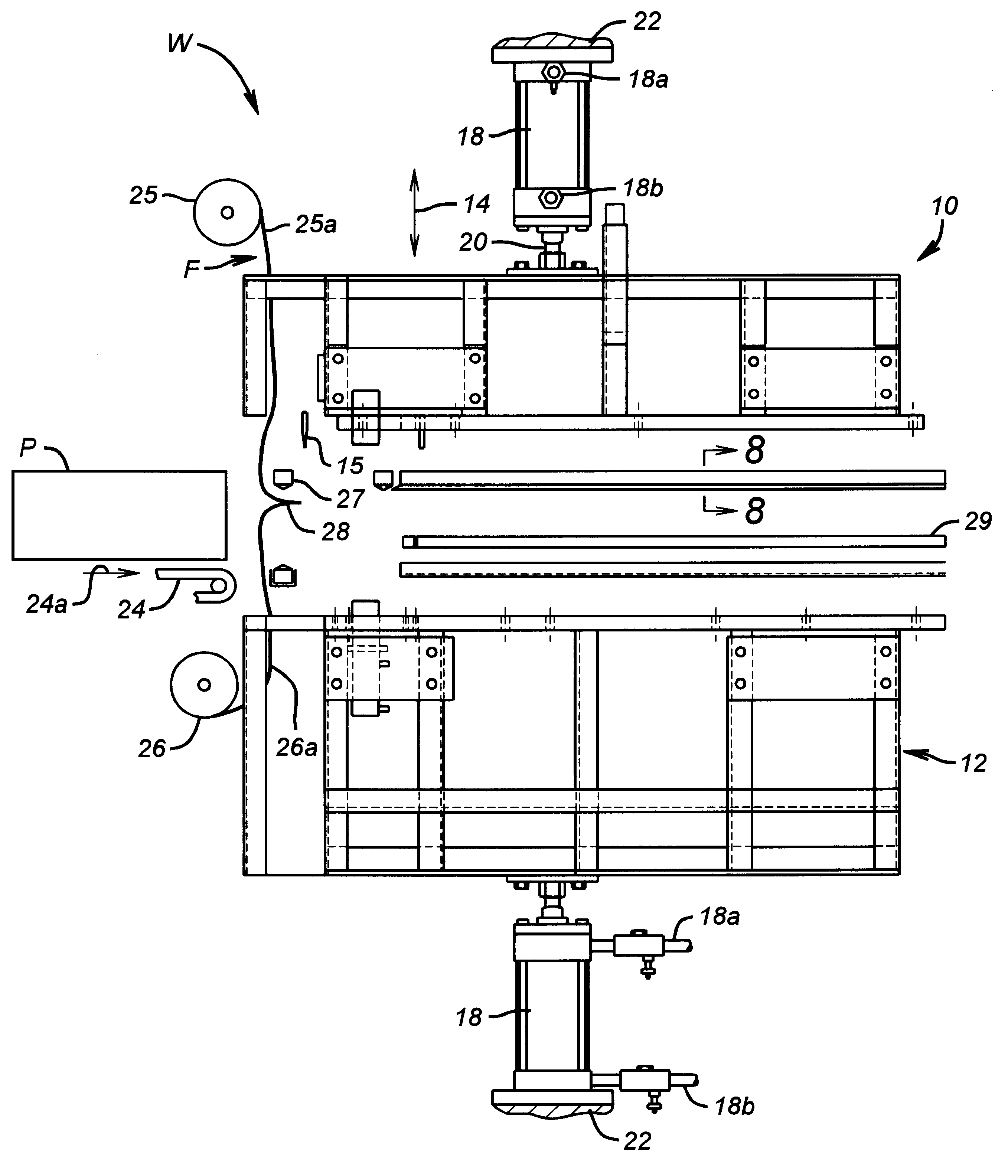
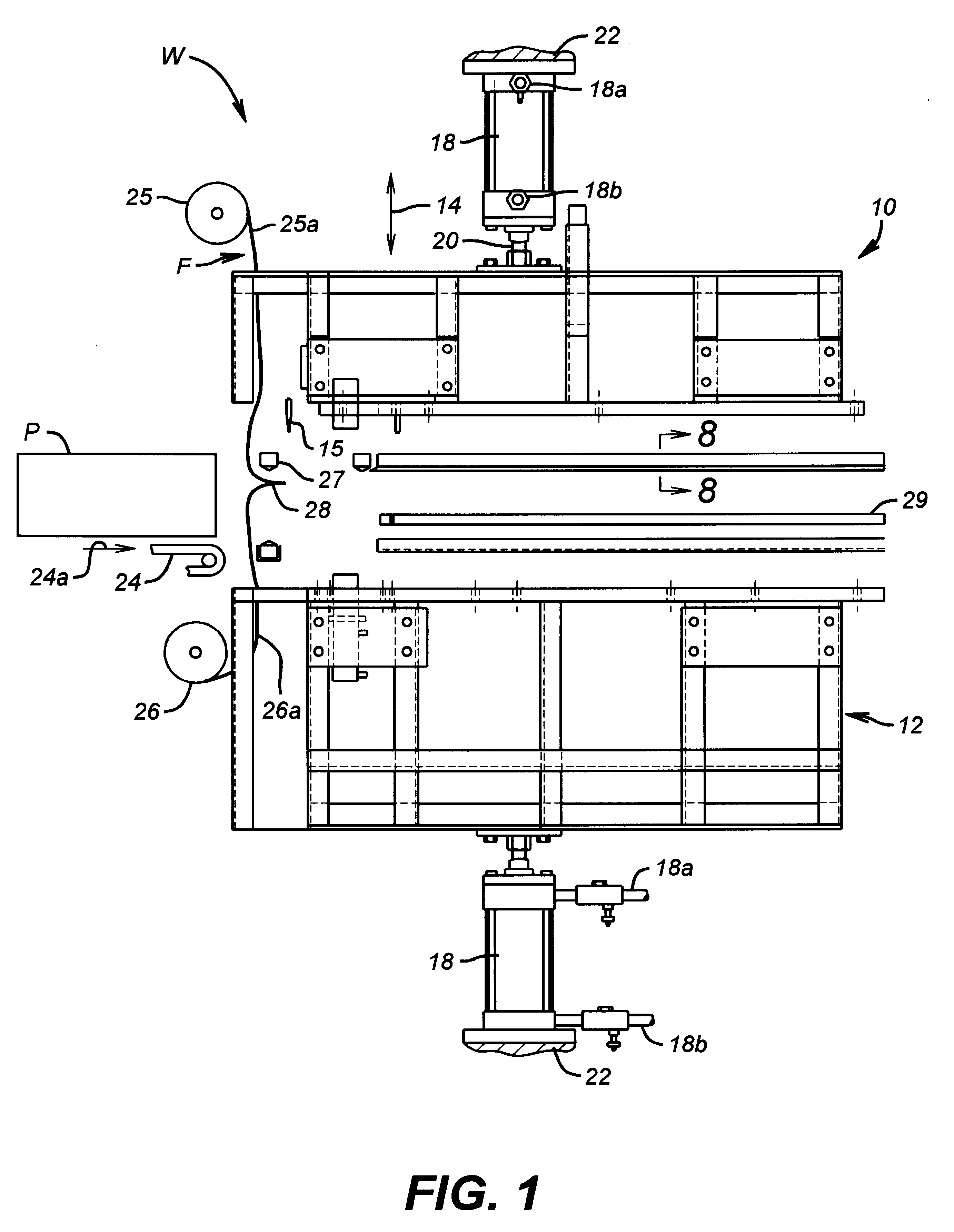
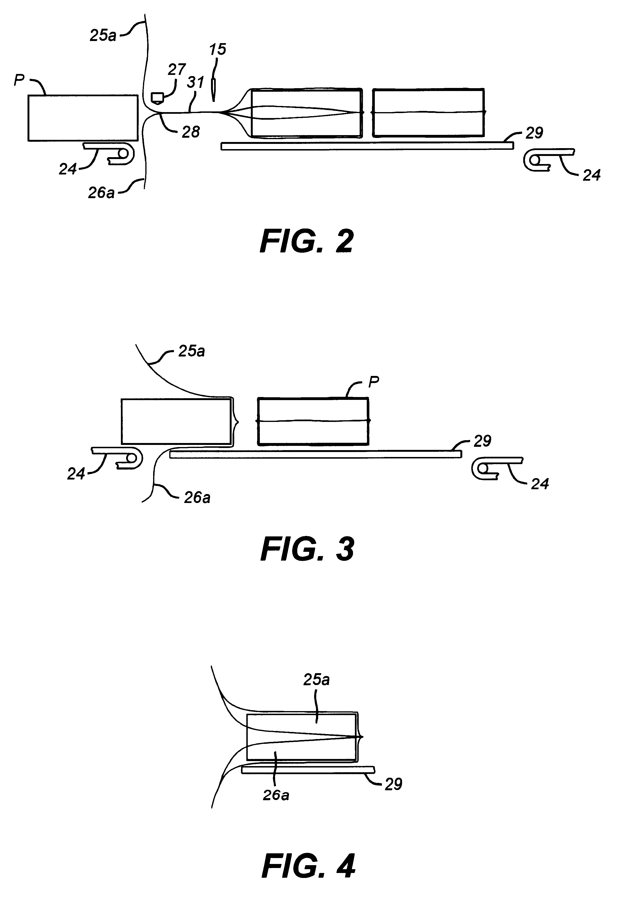
In the drawings, the letter W (FIGS. 1 and 5) designates generally a wrapping machine according to the present invention for wrapping a package P (FIG. 6) into a synthetic resin film F. The wrapping machine W includes a set of jaw members 10 and 12 which in the preferred embodiment are movable support frames. The jaw or frame members 10 and 12 are movable inwardly and outwardly with respect to each other, as indicated by an arrow 14, by a suitable movement mechanism. As shown in the drawing, the movement mechanism for each of the jaw members 10 and 12 may be a hydraulic or pneumatic cylinder 18 mounted with such jaw member. It should be understood that other forms of mechanisms conventional in the art may also be used as movement mechanisms as well.

The cylinder 18 for each such jaw member receives a flow of driving fluid through suitably positioned fluid supply flow ports 18a and 18b. The fluid is received into one of the ports 18a or 18b and pressurized to drive a piston rod 20 to ...


PUM

PropertyMeasurementUnit
heightaaaaaaaaaa
heightaaaaaaaaaa
heightaaaaaaaaaa

Abstract

A machine wraps packages such as bales of crumb rubber, or other containers of goods, into a protective synthetic resin film bag or cover. The machine is provided with a set of movable jaws each having a heat-sealing frame assembly having improved heat transfer characteristics. The heat-sealing frame assembly is composed of heat sealing units which have enhanced heat distribution and reduced cold spot or no-seal areas, and also reduced hot spot burn-through. Heat transfer from the heat sealing elements to the remaining portions of the baling assembly is also reduced.

Description

1. Field of the InventionThe present invention relates to sealing machines for bales or packages, such as high quality rubber crumbs or chips.2. Description of the Related ArtA considerable number of types of packages or cartons are wrapped and then heat sealed into a protective synthetic resin film for shipment. So far as is known, the heat sealing has been done by a set of elongate heat elements formed in the horizontal outline or configuration of the package, usually a rectangle or square. An example of such an elongate heat element or rod is a product known as a Calrod.RTM. sold by General Electric Company. The rod received a flow of electrical current through it and generated heat to partially melt edges of the film together to seal the film into a protective film wrap over the box or product. The heat rod was usually enclosed in a non-adhesive protective cover, such as that sold by E. I. duPont de Nemours and Company under the trademark Teflon.RTM., to prevent the film from st...

Claims


Application Information

Patent Timeline
Patent Type & Authority Patents(United States)
IPC IPC(8): B29C65/18B65B9/00B65B51/14B65B9/02
CPCB29C65/18B29C66/81422B29C66/80B29C66/81821B65B9/026B65B51/14B29C65/305B29C66/81261B29C66/24244B29C65/00B29C66/83221B29C66/81831B29C66/43B29C66/8242B29C66/133
Inventor FRAGSTEIN, KARL H.
Owner KARLTEX MACHINE
Why Eureka
Try Eureka