Web conveyor for a thermoforming apparatus, web support apparatus for a thermoforming apparatus, and thermoformable web support apparatus

a technology of thermoforming apparatus and thermoforming apparatus, which is applied in the direction of printers, instruments, furnaces, etc., can solve the problems of increasing friction, reduce static, or start-up friction, increase the uniformity of heat delivery, and enhance the heat delivery

Inactive Publication Date: 2005-08-04
JERE F IRWIN
View PDF12 Cites 2 Cited by
  • Summary
  • Abstract
  • Description
  • Claims
  • Application Information

AI Technical Summary

Benefits of technology

[0014] The present invention provides an advantage by reducing static, or start-up, friction between a heated web of thermoformable material and a web support structure when intermittently delivering the web so that the web is stationary, then moving, during an intermittent motion thermoforming operation.
[0015] The present invention provides another advantage by increasing uniformity of heat delivery to a web in an oven because the friction-reducing material is elevated above a top edge of a sag rail to provide gaps between the intermittent insert pieces of friction-reducing material. The gaps enhance delivery of heat to the web of material while the web is moved through an oven, or heat tunnel, so as to impart more uniform delivery of heat across and along the web of material.
[0016] The present invention provides yet another advantage in that the web is more uniformly heated by enhancing temperature control of the web supporting apparatus. To achieve this, a temperature regulating system is provided for controlling temperature of a friction-reducing material and an accompanying web support rail to maintain the friction-reducing material within a desired and safe temperature operating range within an oven, or heat tunnel, and to regulate temperature of the rail.

Problems solved by technology

Accordingly, the web moves and stops intermittently, which can tend to increase the friction by imparting static friction between the heated web and the underlying web support apparatus.
Secondly, the web support apparatus incorporates a discrete geometry that supports the web at discrete locations.

Method used


Image

  • Web conveyor for a thermoforming apparatus, web support apparatus for a thermoforming apparatus, and thermoformable web support apparatus
  • Web conveyor for a thermoforming apparatus, web support apparatus for a thermoforming apparatus, and thermoformable web support apparatus
  • Web conveyor for a thermoforming apparatus, web support apparatus for a thermoforming apparatus, and thermoformable web support apparatus

Examples


Embodiment Construction

[0028] This disclosure of the invention is submitted in furtherance of the constitutional purposes of the U.S. Patent Laws “to promote the progress of science and useful arts” (Article 1, Section 8).

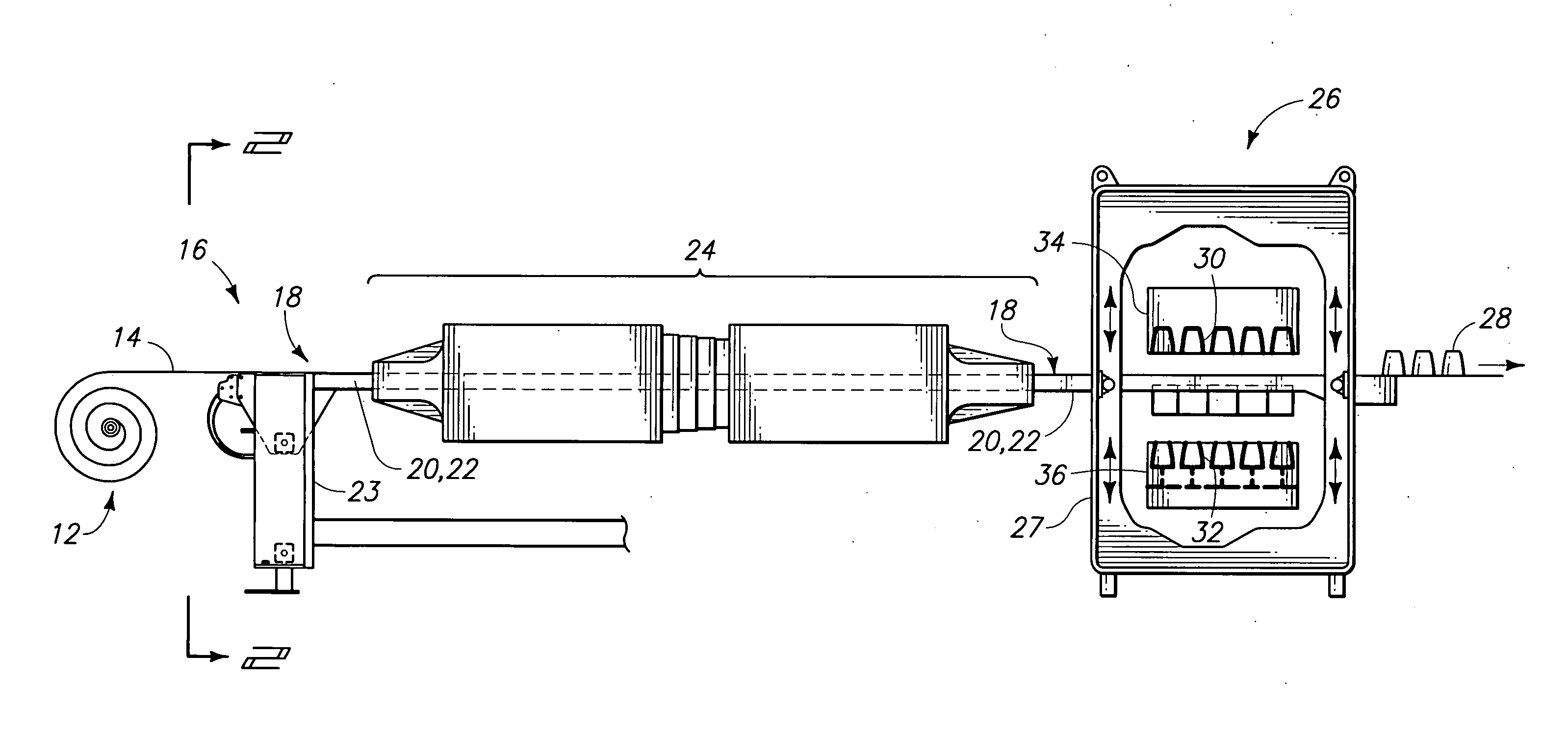
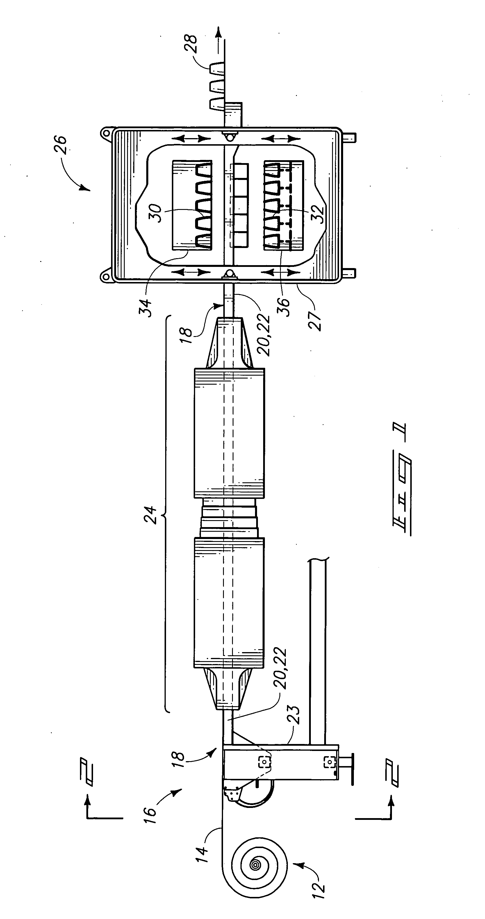
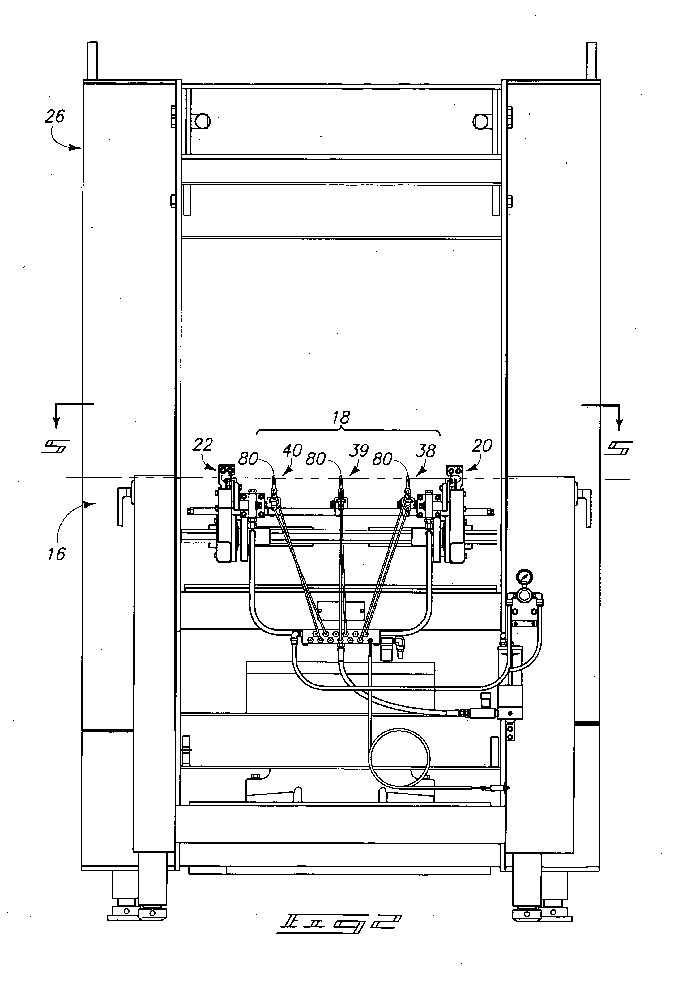
[0029] Reference will now be made to a preferred embodiment of Applicant's invention. An exemplary implementation is described below and depicted with reference to the drawings comprising a web support apparatus and a conveyor having a web support apparatus according to one aspect of the present invention. However, alternative embodiments will be understood and described (where appropriate) with reference to the figures.

[0030] While the invention is described by way of the preferred embodiment, it is understood that the description is not intended to limit the invention to this embodiment, but is intended to cover alternatives, equivalents, and modifications which may be broader than this embodiment, such as are included within the scope of the appended claims.

[0031] Furthermore, in a...


PUM


Abstract

A web conveyor is provided having a frame, a pair of conveyor rails, and at least one sag rail. The pair of conveyor rails is carried by the frame in laterally spaced-apart relation. The pair of conveyor rails is configured to support and convey respective edges of a thermoformable web of plastic material. The at least one sag rail includes a friction-reducing material provided along at least a portion of a top edge of the sag rail. The sag rail is provided between the conveyor rails and extends longitudinally along a web travel path. The sag rail is configured to support a web of material intermediate the conveyor rails. A web support apparatus having one or more of friction-reducing material, local, raised portions, and a temperature regulator is also provided.

Description

RELATED PATENT DATA [0001] This continuation application claims the benefits of U.S. patent application Ser. No. 10 / 460,933, entitled “Web Conveyor and Web Supporting Apparatus”, which was filed Jun. 12, 2003, and which is incorporated by reference herein.TECHNICAL FIELD [0002] This invention pertains to fabrication of plastic products from plastic webs using differential pressure thermoforming apparatus. More particularly, the present invention relates to a web support apparatus and method for limiting sagging of a plastic web of thermoformable material when processing the material through a heating station and into a thermoforming station. BACKGROUND OF THE INVENTION [0003] Thermoforming lines are used to manufacture and form a variety of plastic, thin-walled articles by processing a continuous web or sheet of thermoformable plastic material. One particular technique involves the use of continuous web, differential pressure, thermoforming machines which encounter a problem wherein...

Claims


Application Information

Patent Timeline
Patent Type & Authority Applications(United States)
IPC IPC(8): B65H23/28
CPCB65H23/28
Inventor IRWIN, JERE F.VANTREASE, DALE L.
Owner JERE F IRWIN
Why Eureka
Try Eureka