Antenna device and electronic device having the same

a technology of electronic devices and antenna devices, applied in the field of antenna devices, can solve problems such as difficulties in additionally securing a space for disposing such antenna devices within electronic devices

Active Publication Date: 2020-05-07
SAMSUNG ELECTRONICS CO LTD
View PDF2 Cites 2 Cited by
  • Summary
  • Abstract
  • Description
  • Claims
  • Application Information

AI Technical Summary

Benefits of technology

[0011]To address the above-discussed deficiencies, it is a primary object to provide an antenna device that is capable of securing a radiating performance that is stable in the mmWave band even though the antenna device is installed together with the antenna devices that operate in commercially available frequency bands.
[0012]In addition, various embodiments of the present disclosure are to provide an antenna device that enables an antenna of the mmWave band to be mounted while maintaining the design of an existing miniaturized and slimmed electronic device, thereby contributing to the commercialization of the antenna device.
[0015]According to various embodiments of the present disclosure, while transmitting / receiving a wireless signal in a first frequency band (e.g., a mmWave band) by using the radiators that are provided with a first feeding signal and a ground that provides a reference potential for the radiators, the antenna device may provide a second feeding signal to the radiators or the ground to transmit / receive a wireless signal in a second band (e.g., a commercially available frequency band). In addition, according to various embodiments of the present disclosure, it is possible to implement an antenna device that may provide a communication function in a second frequency band by using a portion of an antenna device that provides a communication function in a first frequency band, thereby reducing a space in which antennas are mounted within an electronic device.

Problems solved by technology

When antenna devices are additionally installed to trans / receive a wireless signal in the mmWave band, there may be difficulties in additionally securing a space for disposing such antenna devices within the electronic device.

Method used


Image

  • Antenna device and electronic device having the same
  • Antenna device and electronic device having the same
  • Antenna device and electronic device having the same

Examples


Embodiment Construction

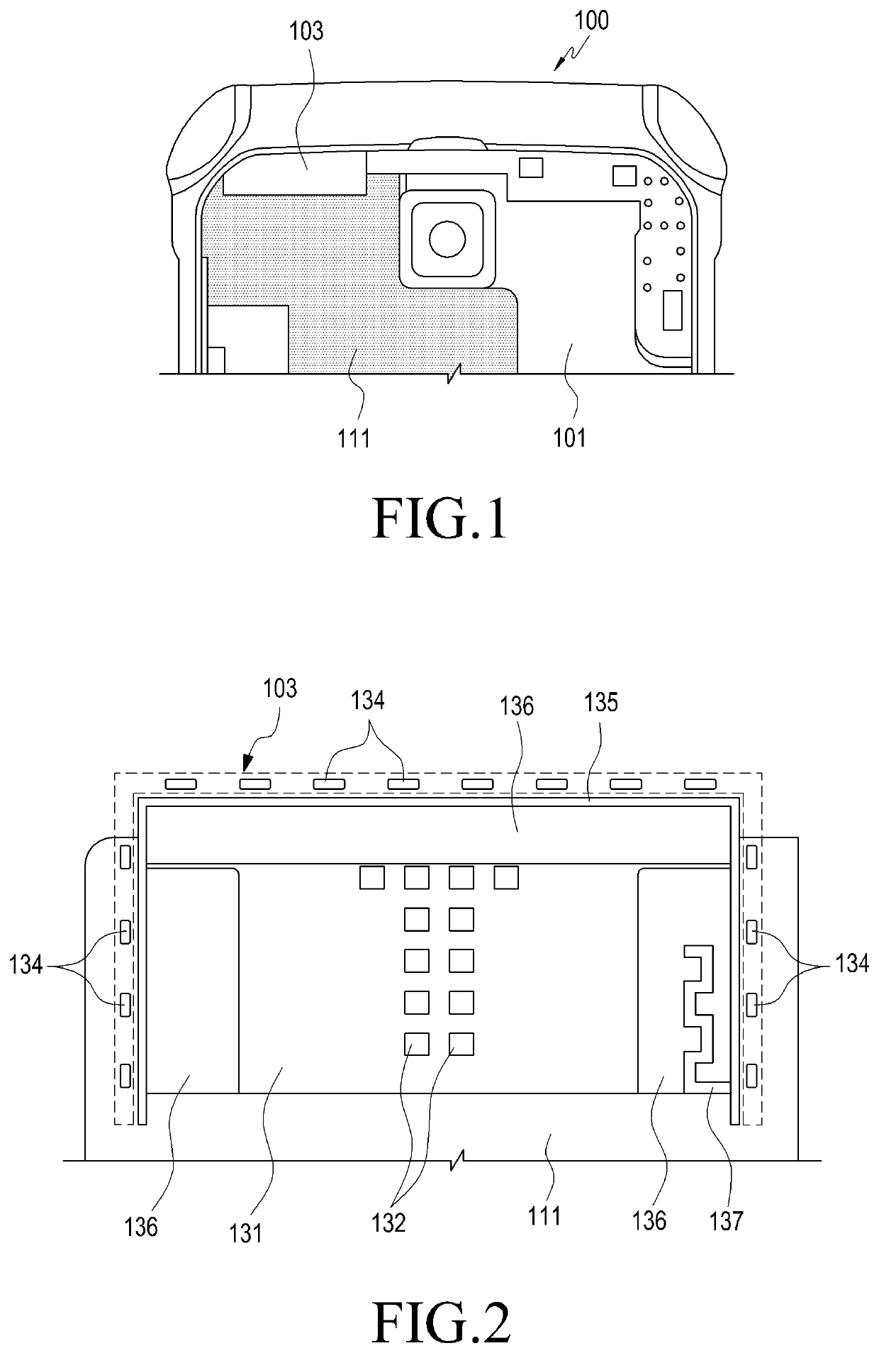
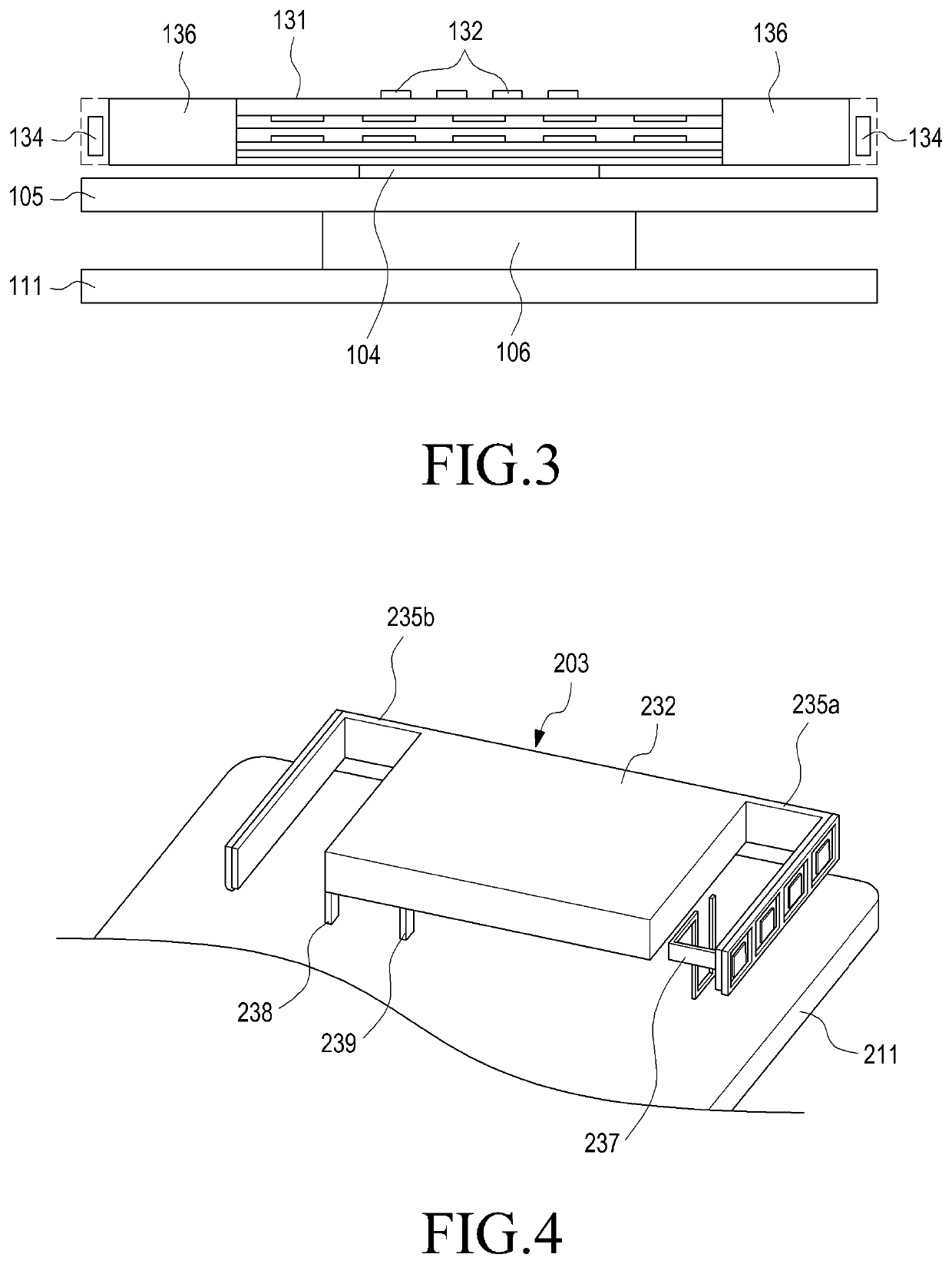
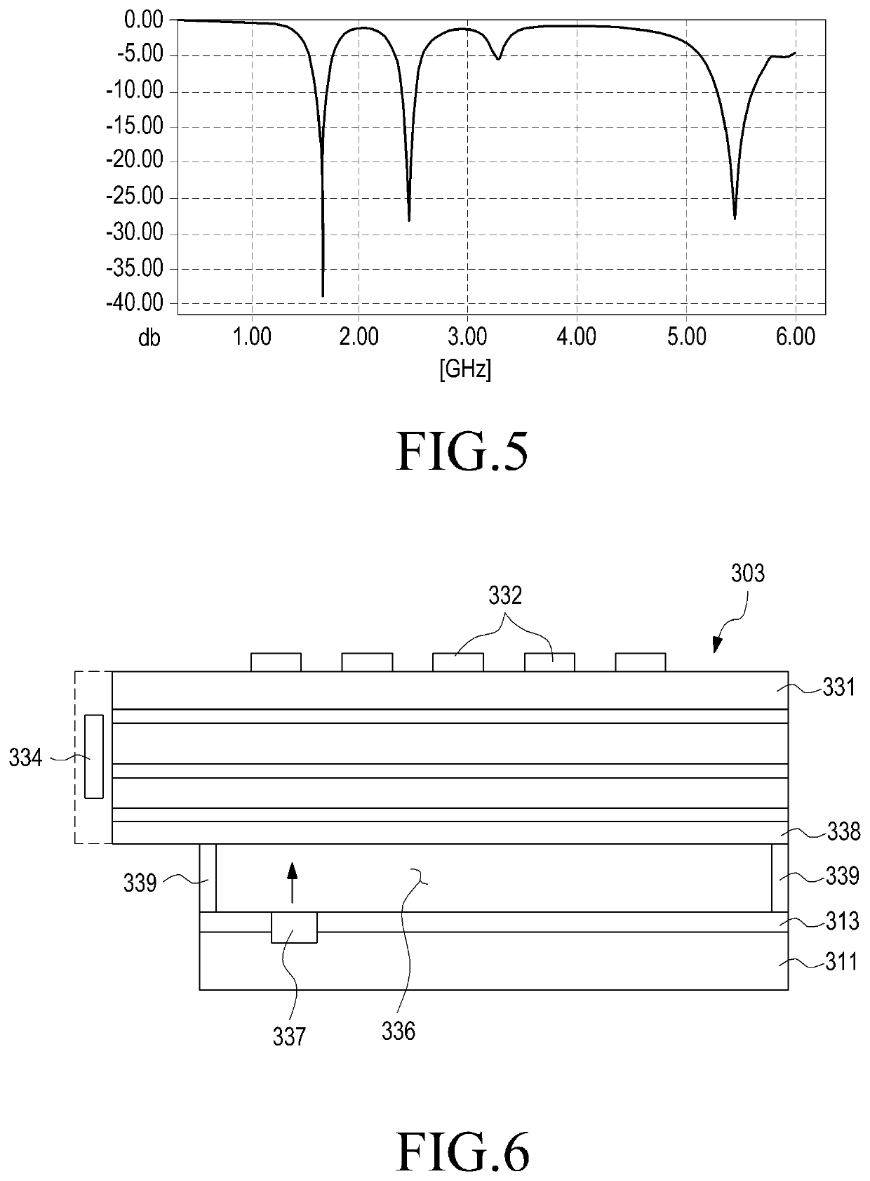
[0035]FIGS. 1 through 17, discussed below, and the various embodiments used to describe the principles of the present disclosure in this patent document are by way of illustration only and should not be construed in any way to limit the scope of the disclosure. Those skilled in the art will understand that the principles of the present disclosure may be implemented in any suitably arranged communication devices.

[0036]Hereinafter, various embodiments of the present disclosure will be described with reference to the accompanying drawings. The embodiments and the terms used therein are not intended to limit the technology disclosed herein to specific forms, and should be understood to include various modifications, equivalents, and / or alternatives to the corresponding embodiments. In describing the drawings, similar reference numerals may be used to designate similar constituent elements. As used herein, singular forms may include plural forms as well unless the context clearly indicat...


PUM


Abstract

An electronic device may include a circuit board, radiators disposed on the circuit board, and provided with a first feeding signal to transmit or receive a wireless signal in a first frequency, band; and a ground disposed on the circuit board to provide a reference potential for the radiators. The radiators and a whole or a portion of the ground may be provided with an additional feeding signal to transmit or receive a wireless signal in various frequency bands that are lower than the first frequency band.

Description

CROSS-REFERENCE TO RELATED APPLICATIONS[0001]This application is a continuation of application Ser. No. 15 / 411,568, filed Jan. 20, 2017, which claims priority to Korean Application No. 10-2016-0007714, filed Jan. 21, 2016, the entire contents of which are hereby incorporated by reference,BACKGROUNDField[0002]Various embodiments of the present disclosure relate to an antenna device. For example, various embodiments of the present disclosure relate to an antenna device that is provided in an electronic device.Description of Related Art[0003]Efforts have been made to develop a 5G (5th-generation) communication system or a pre-5G communication system in order to satisfy a demand for wireless data traffic which is on an increasing trend after the commercialization of the 4G (4th-generation) communication system. Due to this, the 5G communication or the pre-5G communication system is referred to as a “beyond 4G network communication system” or a “post LTE system.”[0004]In order to achieve...

Claims


Application Information

Patent Timeline
Patent Type & Authority Applications(United States)
IPC IPC(8): H01Q1/38H01Q1/22H01Q1/48H01Q5/42H01Q21/29H01Q5/40H01Q1/52H01Q3/24H01Q9/42H01Q9/04H01Q21/28
CPCH01Q5/42H01Q1/523H01Q21/293H01Q9/42H01Q1/38H01Q1/48H01Q21/064H01Q21/065H01Q1/2291H01Q21/28H01Q5/40H01Q9/0407H01Q3/24
Inventor LEE, YOUNG-JUKIM, HYUN-JINPARK, JUNG-MIN
Owner SAMSUNG ELECTRONICS CO LTD
Why Eureka
Try Eureka