
Tire maintenance support system, tire maintenance support program, and tire maintenance support method

Inactive Publication Date: 2020-05-14
BRIDGESTONE CORP
View PDF0 Cites 0 Cited by
  • Summary
  • Abstract
  • Description
  • Claims
  • Application Information

AI Technical Summary

Benefits of technology

The patent text describes a system, program, and method to support the maintenance of tires on a route bus while minimizing the downtime of the vehicle. The system uses sensors to monitor the wear of the tire tread and side portion, and sends signals to a central computer to make recommendations on when to replace the tire. These recommendations are based on the vehicle's maintenance schedule, and the system ensures that the tire maintenance is performed at the same time as the vehicle's inspection. This approach helps to improve the precision docking of the route bus, which enhances the performance of getting on / off for passengers.

Problems solved by technology

However, when the precision docking is improved, a surface of a side portion (side wall) of a tire is rubbed with a curbstone of a sidewalk and a side portion is severely worn.

Method used


Image

  • Tire maintenance support system, tire maintenance support program, and tire maintenance support method
  • Tire maintenance support system, tire maintenance support program, and tire maintenance support method
  • Tire maintenance support system, tire maintenance support program, and tire maintenance support method

Examples


example 1

(2. 2. 1) Operation Example 1

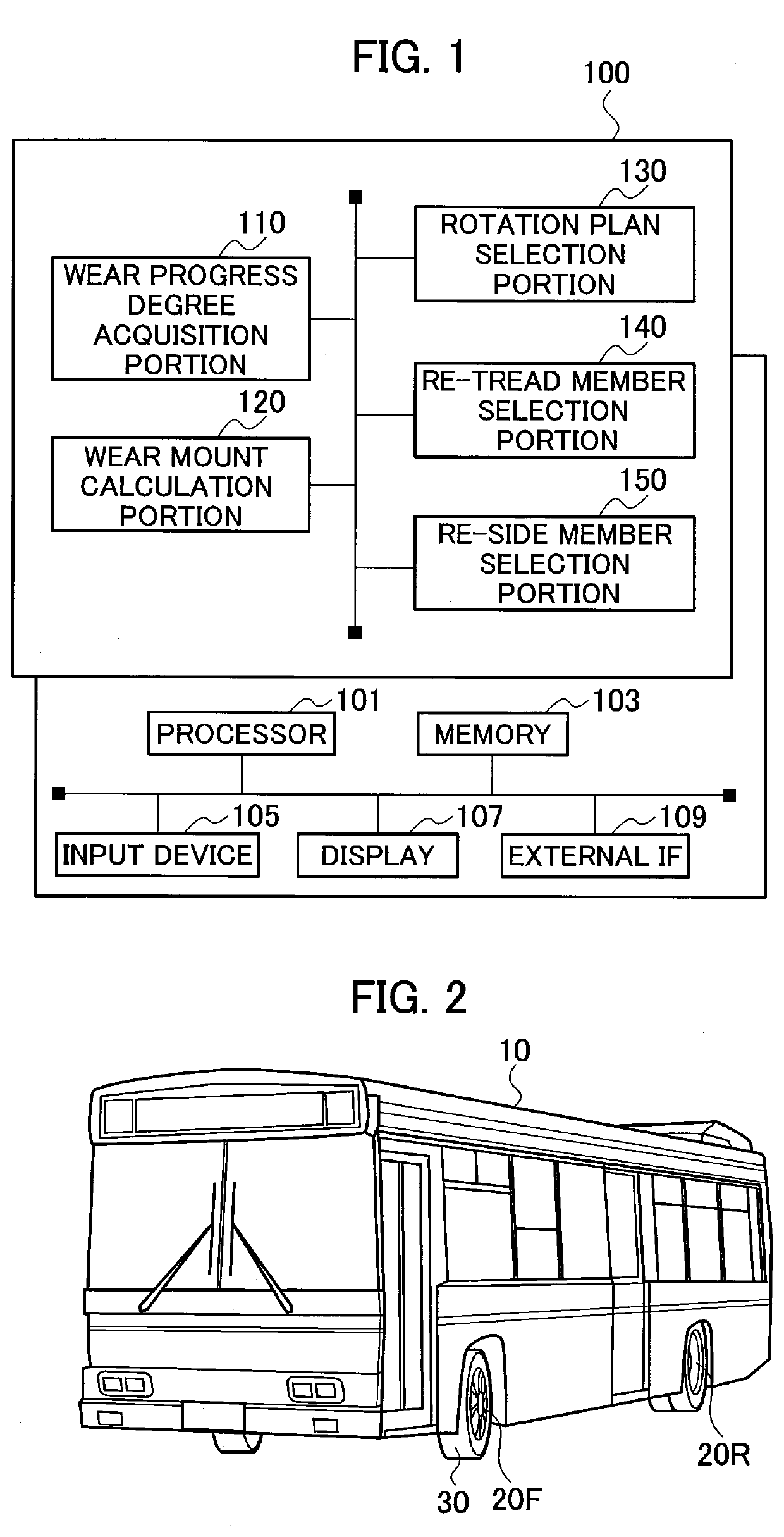
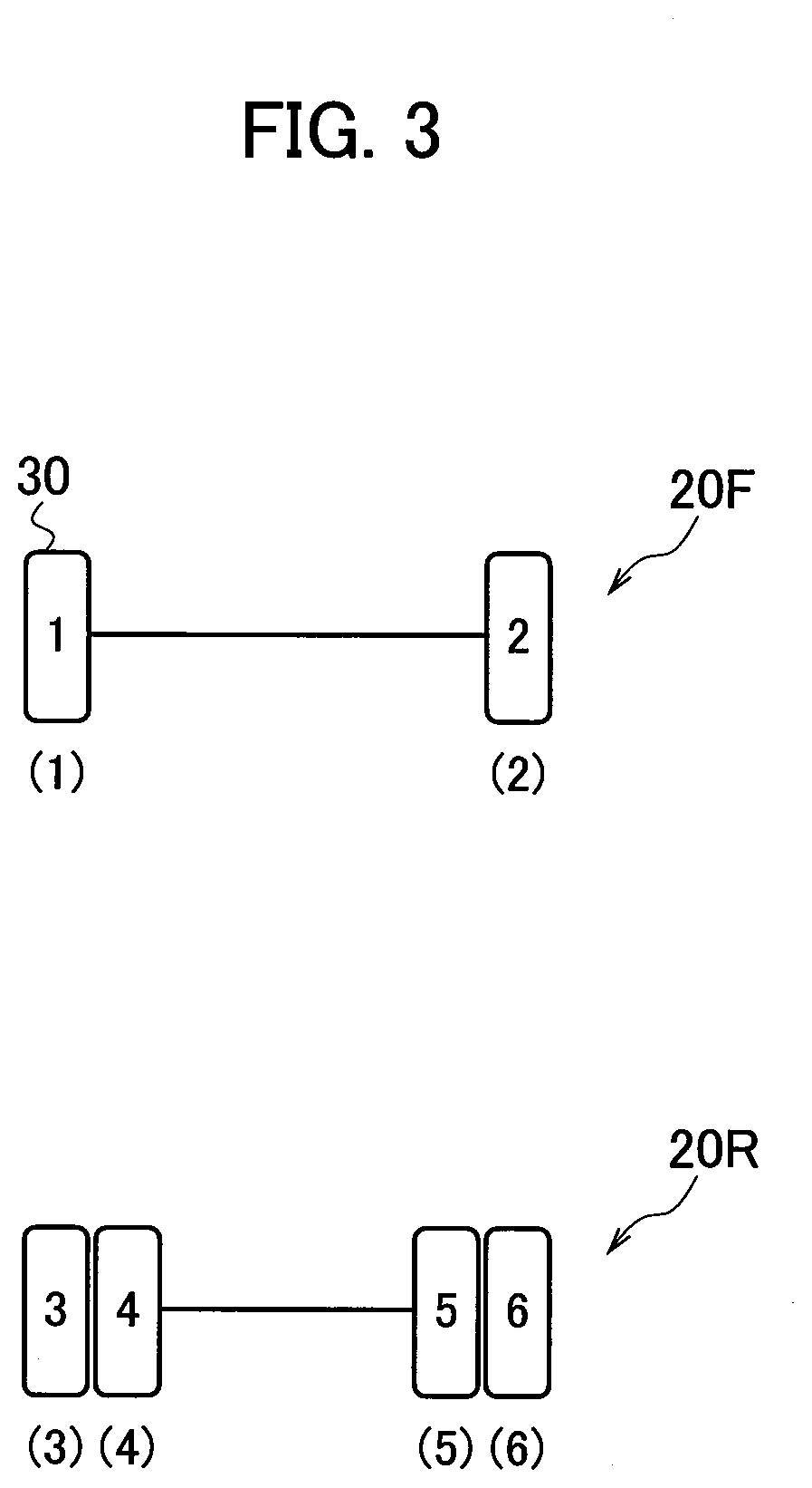
[0082]FIG. 6 is a flow chart illustrating the selective flow (operation example 1) of the rotation plan of the tires 30. As shown in FIG. 6, the tire maintenance support system 100 decides combinations (maximum 720 combinations) of the mount positions and the tires 30 (Tire 1 to 6) to be subjected to the rotation, based on POS. 1 to 6 and Tire 1 to 6 (S110). Here, the tire maintenance support system 100 can exclude the combination in which the rotation is difficult due to difference in specifications of the tires.

[0083]The tire maintenance support system 100 calculates the predicted wear amount until the next maintenance timing (t1 or t2) of each of Tire 1 to 6 in each combination (S120).

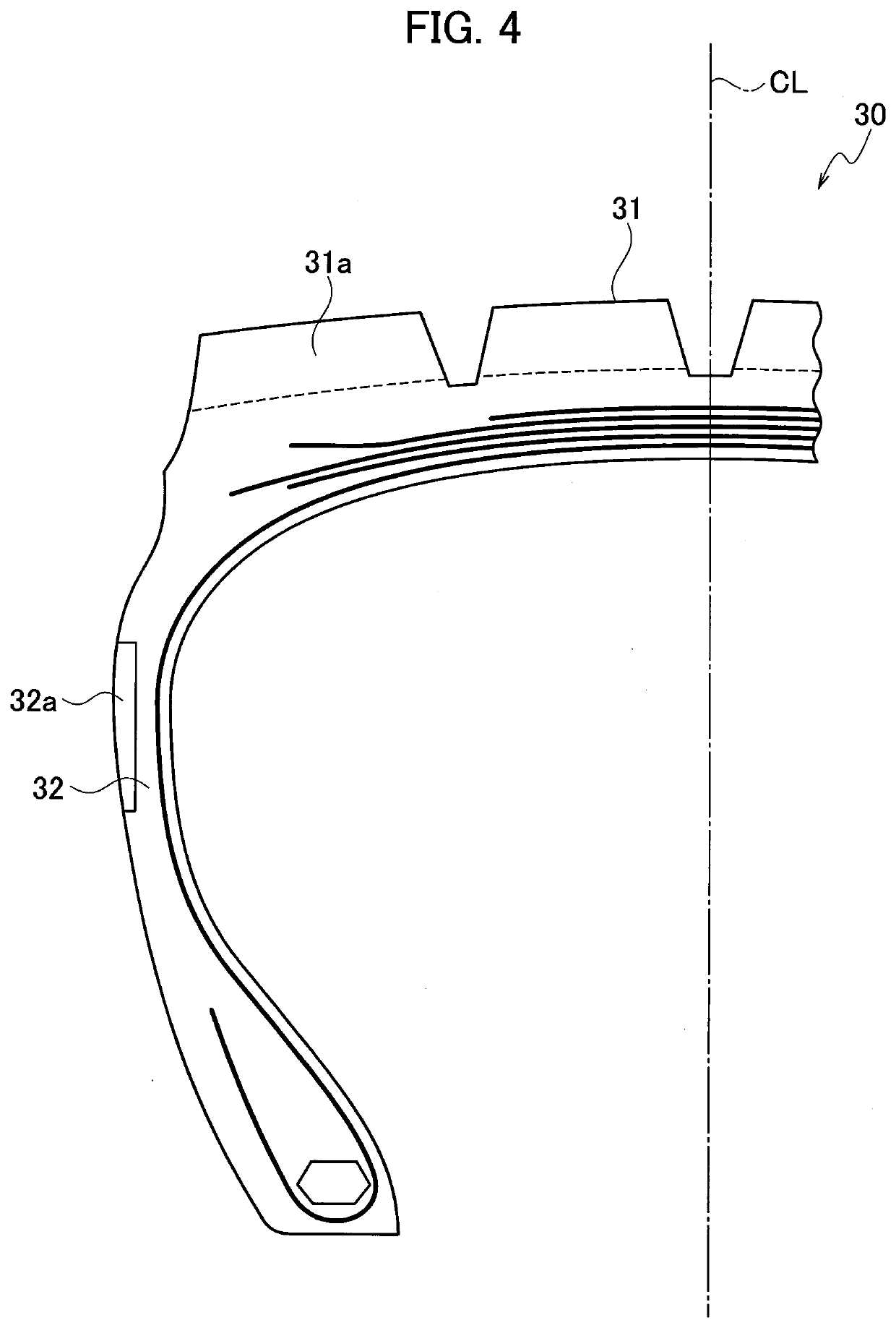
[0084]Table 1 shows the predicted wear amounts (tread 31 and side portion 32) until the maintenance timing t2 in each combination of the rotation. Here, the value in Table 1 shows the predicted wear amount, however it is not always equal to a specific value (for example,...

example 2

(2. 2. 2) Operation Example 2

[0096]FIG. 7 is a flow chart illustrating a selective flow (operation example 2) of the rotation plan of the tires 30. Hereinafter, a configuration of the operation example 2 different from that of the operation example 1 described above is mainly described, and therefore a description of a similar configuration is omitted as needed.

[0097]The processes of S210 to S230 shown in FIG. 7 are similar to the processes of S110 to S130 shown in FIG. 6. As shown in FIG. 7, in a case in which the re-tread or the re-side is not necessary, the tire maintenance support system 100 selects the rotation plan in which the sum δ of the differences between the predicted wear amount of the tread 31 and the predicted wear amount of the side portion 32 in the tires 30, namely Tire 1 to 6, is minimum (S240).

[0098]The processes of S250 and S260 are similar to the processes of S150 and S160 shown in FIG. 6, respectively.

[0099]FIG. 12A and FIG. 12B shows a rotation example (opera...


PUM


Abstract

A tire maintenance support system includes a wear progress degree acquisition portion that acquires a wear progress degree of each of a tread and a side portion in each mount position, a wear amount calculation portion that calculates a predicted wear amount, which is a wear amount of each of the tread and the side portion in each mount position until maintenance timing when maintenance of the vehicle is performed, based on the acquired wear progress degree, and a re-tread member selection portion and a re-side member selection portion that select a thickness of a member to be needed when at least one of the tread and the side portion is replaced, based on the calculated predicted wear amount.

Description

TECHNICAL FIELD[0001]The present invention relates to a tire maintenance support system, a tire maintenance support program, and a tire maintenance support method that support maintenance of a tire mounted to a predetermined position of a vehicle.BACKGROUND ART[0002]In recent years, a solution business combining a tire sale and maintenance thereafter has been paid attention instead of a conventional business only selling a tire, especially a pneumatic tire for trucks or buses (hereinafter, called a tire). Accordingly, customers can get benefit to reduce a cost and a management man-hour and thereby regular customers for a tire manufacturer are increased, so that improvement of competitive power of the tire manufacturer is expected.[0003]The maintenance after selling the tire includes management of inner pressure, rotation in mount positions of tires, and re-tread that replaces a worn tread (for example, Non Patent Literature 1).CITATION LISTNon Patent Literature[0004][Non-PTL 1]“Tire...

Claims


Application Information

Patent Timeline
IPC IPC(8): B60C11/24G07C5/00G06Q10/00
CPCB60C2011/0033B60Y2200/143G07C5/006G06Q10/20B60C11/246G06Q10/00G06Q50/40
Inventor OKI, FUTOSHIIKENOMOTO, AYAKA
Owner BRIDGESTONE CORP
Learn More