
Passenger drone collision avoidance via Air Traffic Control over wireless network

Active Publication Date: 2020-05-21
METAL RAPTOR LLC
View PDF0 Cites 3 Cited by
  • Summary
  • Abstract
  • Description
  • Claims
  • Application Information

AI Technical Summary

Benefits of technology

The present patent application is a continuation-in-part of previous patent applications and is related to air traffic control systems for passenger drones. The technical effects of the patent text include incorporating obstruction detection in air traffic control systems for passenger drones, utilizing wireless networks for air traffic control, and incorporating geographic boundaries for management. The patent text also describes various methods for drone air traffic control, such as flying lane management and weather updates. These technical effects enhance the safety and efficiency of air travel for drones and improve the overall air traffic control system.

Problems solved by technology

However, it is impractical to use the existing air traffic control network for drones because of the sheer quantity of drones.

Method used


Image

  • Passenger drone collision avoidance via Air Traffic Control over wireless network
  • Passenger drone collision avoidance via Air Traffic Control over wireless network
  • Passenger drone collision avoidance via Air Traffic Control over wireless network

Examples


example hardware

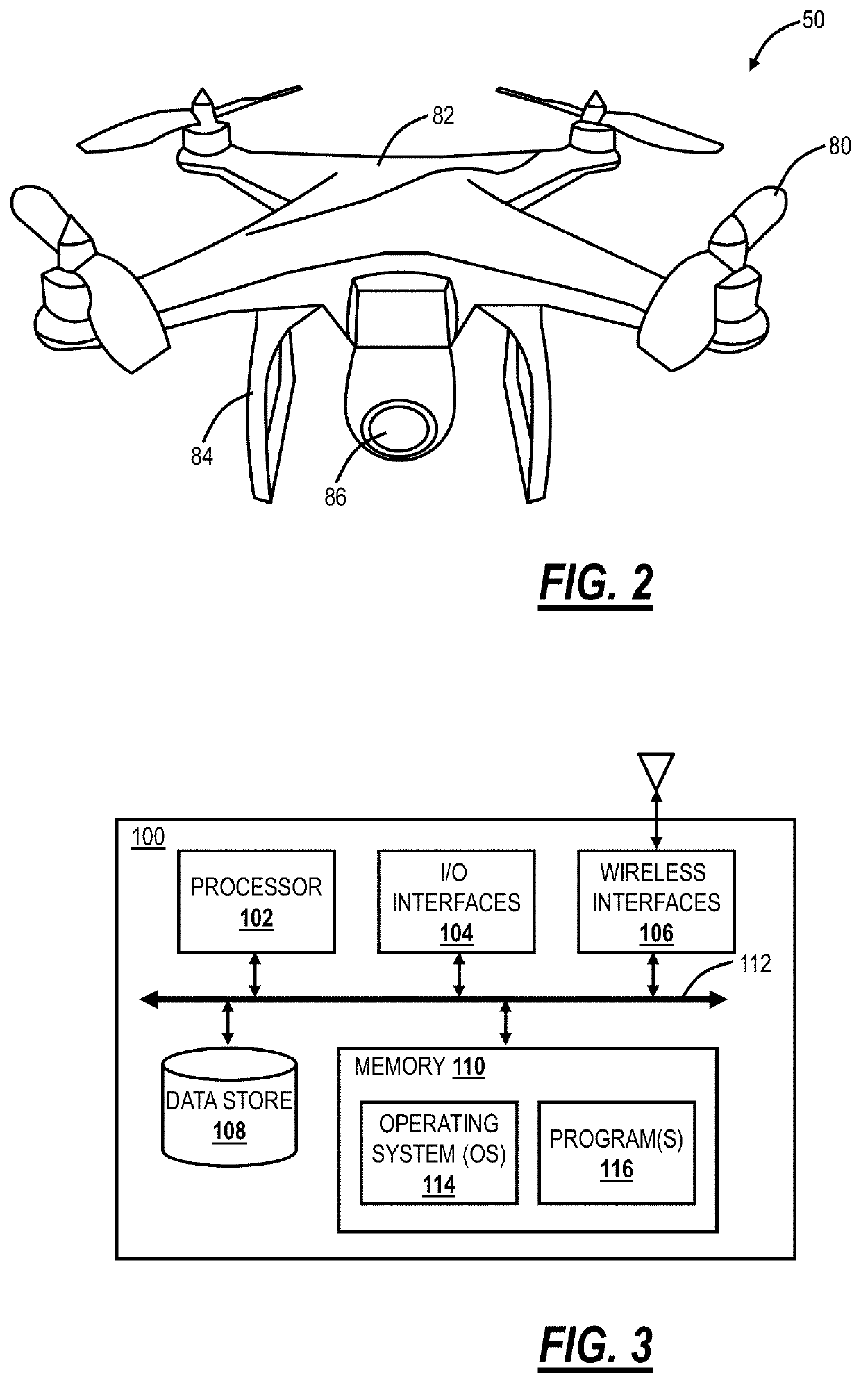
[0064]FIG. 2 is a perspective view of an example UAV 50 for use with the systems and methods described herein. Again, the UAV 50 may be referred to as a drone or the like. The UAV 50 may be a commercially available UAV platform that has been modified to carry specific electronic components as described herein to implement the various systems and methods. The UAV 50 includes rotors 80 attached to a body 82. A lower frame 84 is located on a bottom portion of the body 82, for landing the UAV 50 to rest on a flat surface and absorb impact during landing. The UAV 50 also includes a camera 86 which is used to take still photographs, video, and the like. Specifically, the camera 86 is used to provide a real-time display on the screen. The UAV 50 includes various electronic components inside the body 82 and / or the camera 86 such as, without limitation, a processor, a data store, memory, a wireless interface, and the like. Also, the UAV 50 can include additional hardware, such as robotic arm...

example server

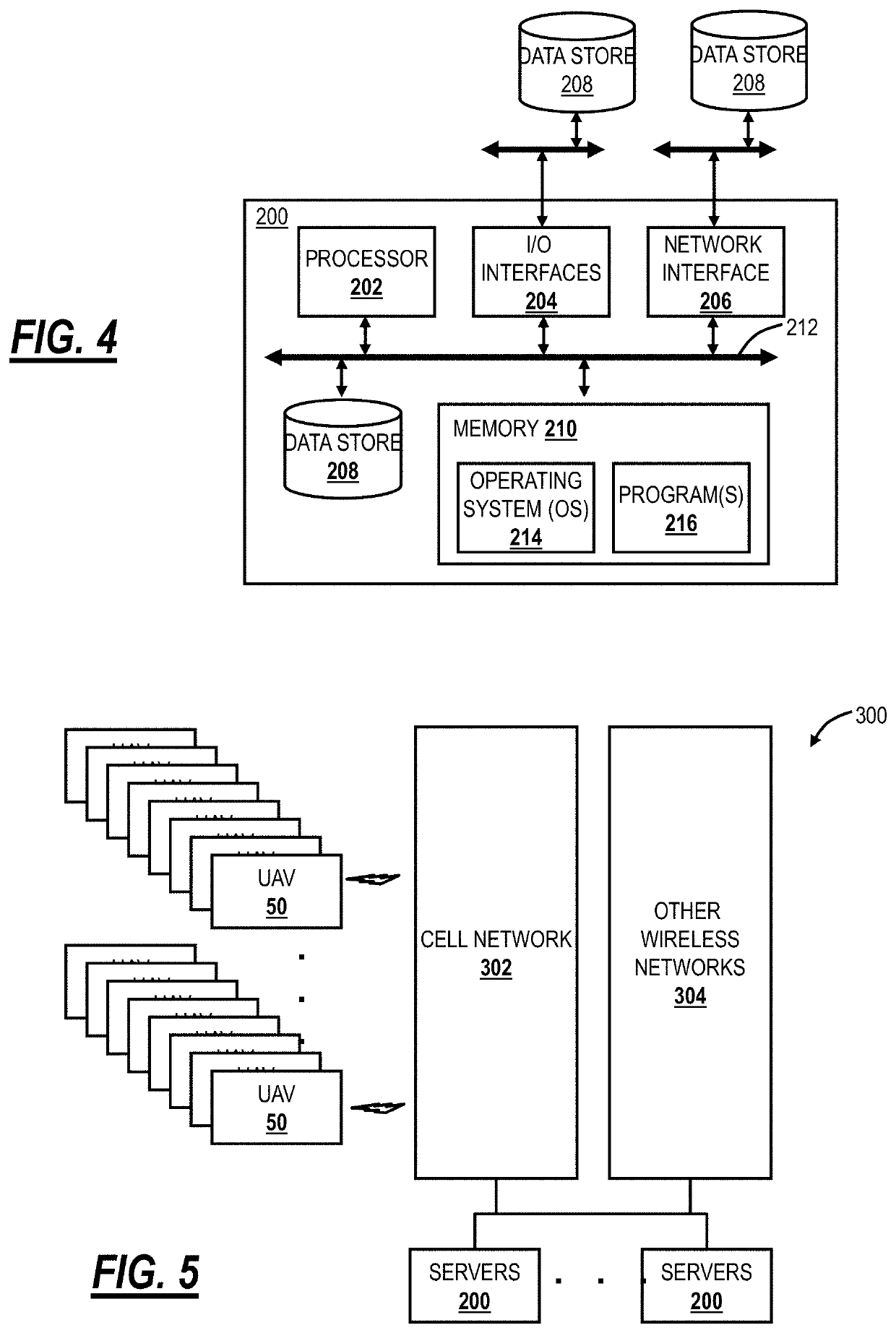
[0072]FIG. 4 is a block diagram of a server 200 which may be used for air traffic control of the UAVs 50. The server 200 may be a digital computer that, in terms of hardware architecture, generally includes a processor 202, input / output (I / O) interfaces 204, a network interface 206, a data store 208, and memory 210. It should be appreciated by those of ordinary skill in the art that FIG. 4 depicts the server 200 in an oversimplified manner, and a practical embodiment may include additional components and suitably configured processing logic to support known or conventional operating features that are not described in detail herein. The components (202, 204, 206, 208, and 210) are communicatively coupled via a local interface 212. The local interface 212 may be, for example, but not limited to, one or more buses or other wired or wireless connections, as is known in the art. The local interface 212 may have additional elements, which are omitted for simplicity, such as controllers, b...


PUM


Abstract

An air traffic control system includes one or more servers each including a network interface, a processor, and memory; and a database communicatively coupled to the one or more servers, wherein the network interface in each of the one or more servers is communicatively coupled to one or more passenger drones via a plurality of wireless networks at least one of which comprises a cellular network; wherein the one or more servers are configured to obtain operational data from a passenger drone, obtain conditions from one or more of the operational data and the database, determine a future flight plan based on the operational data and a flying lane assignment for the passenger drone, determine potential collisions in the future flight plan based on static obstructions and dynamic obstructions, obtained from the database based on the future flight plan, and provide evasive maneuver instructions to the passenger drone.

Description

CROSS-REFERENCE TO RELATED APPLICATION(S)[0001]The present patent / application is continuation-in-part of, and the content of each is incorporated by reference hereinFiling DateSer. No.TitleOct. 2, 201916 / 590,516Emergency shutdown and landing for passenger drones andunmanned aerial vehicles with air traffic control systemsAug. 20, 201916 / 545,051Managing detected obstructions in air traffic control systems forpassenger dronesJul. 15, 201916 / 511,262Obstruction detection in air traffic control systems for passengerdronesJul. 15, 201916 / 511,228Air traffic control monitoring systems and methods for passengerdronesJun. 17, 201916 / 442,597Flying lane management systems and methods for passenger dronesMay 21, 201916 / 417,805Air traffic control of passenger drones concurrently using a pluralityof wireless networksNov. 16, 201816 / 193,053Systems and methods for air traffic control for passenger dronesOct. 9, 201816 / 155,354Systems and methods for drone air traffic control utilizinggeographic bound...

Claims


Application Information

Patent Timeline
IPC IPC(8): G08G5/00G08G5/04G08G5/06B64C39/02
CPCG08G5/0034B64C2201/146G08G5/045H04W4/44H04B7/18506B64C2201/027G08G5/0043G08G5/06B64C39/024G08G5/0013G08G5/0026G08G5/0039G08G5/0069G08G5/0082H04W4/40H04W4/02H04W4/90H04W4/021B64U10/13B64U2201/20B64U20/87B64U30/20
Inventor PRIEST, LEE
Owner METAL RAPTOR LLC
Learn More