Robot cleaner
a robot cleaner and cleaner technology, applied in the field of robot cleaners, can solve the problems of limited cleaning area and inability to clean other than the floor, and achieve the effects of avoiding dust suction performance degrade, facilitating movement, and effective cleaning operation
- Summary
- Abstract
- Description
- Claims
- Application Information
AI Technical Summary
Benefits of technology
Problems solved by technology
Method used
Image
Examples
first embodiment
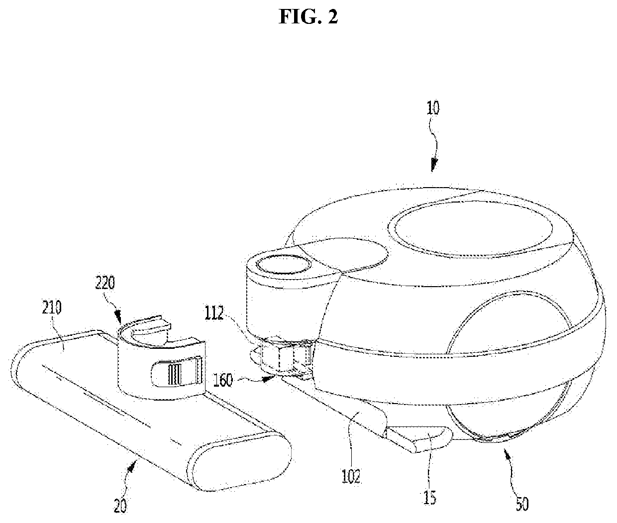
[0063]FIG. 7 is a view illustrating a second module connection part according to the present invention, FIG. 8 is a view illustrating a state in which the second module connection part of FIG. 7 is located at a first position of the main body, and FIG. 9 is a view illustrating a passage in the main body in the state in which the second module connection part of FIG. 7 is located at the first position of the main body. FIG. 10 is a view illustrating a state in which the second module connection part of FIG. 7 is located at a second position of the main body, FIG. 11 is a view illustrating a passage in the main body in the state in which the second module connection part of FIG. 10 is located at the second position of the main body, and FIG. 12 is a view illustrating a state in which a second suction module is connected to the second module connection part. Referring to FIGS. 7 to 12, the main body 10 may further include a second module connection part (or second connector) 120 to whi...
third embodiment
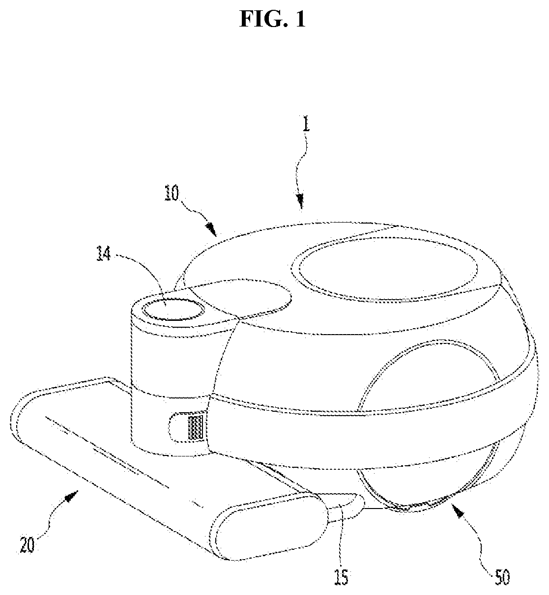
[0085]Referring to FIGS. 1, 12 and 15, a robot cleaner 1 according to the present invention may include a motor 510 which generates a driving force for automatically moving a main body, and a wheel 530 which is rotated by the motor 510. The robot cleaner 1 may further include a controller 13 for controlling the motor 510, and an input part 14 for inputting various commands. Also, the robot cleaner 1 may further include a clutch 520 which blocks a driving force of the motor 510 from being transmitted to the wheel 530.
[0086]An automatic cleaning mode and a manual cleaning mode may be selected using the input part 14. The automatic cleaning mode is a mode in which the robot cleaner 1 performs a cleaning operation while automatically traveling. In the automatic cleaning mode, the air and the dust may be suctioned through the first suction module 20. The manual cleaning mode is a mode in which the cleaning operation is manually performed in a state in which the user connects the second s...
fourth embodiment
[0091]Referring to FIGS. 12 and 16, a robot cleaner according to the present invention may include a motor 510 for automatically moving the robot cleaner, and a controller 13 for controlling the motor 510. Also, the robot cleaner may further include an installation detecting part 16 for detecting an installation of the second suction module 60.
[0092]The controller 13 may control the motor 510 based on whether the installation of the second suction module 60 is detected by the installation detecting part 16. When a command for operating the suction motor is input while the installation detecting part 16 detects a fact that the second suction module 60 is not yet installed, the controller 510 may control the motor 510 so that the robot cleaner 1 is moved in a preset traveling pattern. The preset traveling pattern may include various patterns such as a random pattern and a zigzag pattern.
[0093]When the command for operating the suction motor is input while the installation detecting pa...
PUM
 Abstract
Description
Claims
Application Information
 - R&D
- Intellectual Property
- Life Sciences
- Materials
- Tech Scout
- Unparalleled Data Quality
- Higher Quality Content
- 60% Fewer Hallucinations
Browse by: Latest US Patents, China's latest patents, Technical Efficacy Thesaurus, Application Domain, Technology Topic, Popular Technical Reports.
© 2025 PatSnap. All rights reserved.Legal|Privacy policy|Modern Slavery Act Transparency Statement|Sitemap|About US| Contact US: help@patsnap.com


