Webbing retractor

a retractor and webbing technology, applied in vehicle components, vehicle safety belts, transportation and packaging, etc., can solve the problems of restricted pulling out of webbing, and achieve the effect of accurate operation, small acceleration of webbing, and accurate operation

Inactive Publication Date: 2020-06-04
KK TOKAI RIKA DENKI SEISAKUSHO
View PDF0 Cites 0 Cited by
  • Summary
  • Abstract
  • Description
  • Claims
  • Application Information

AI Technical Summary

Benefits of technology

[0019]As described above, because the wound diameter of the webbing at the take-up shaft changes in accordance with the pulled-out amount of the webbing, in a case in which the wound diameter of the webbing is not corrected, the more the webbing is pulled-out, the smaller the acceleration of the webbing is computed to be. Thus, in accordance with this webbing retractor, by correcting the threshold value, which is the object of comparison with the acceleration, instead of correcting the acceleration, the locking mechanism can be operated accurately.
[0020]In the webbing retractor of the fifth aspect, the pulled-out amount of the webbing is used in acquiring the acceleration of the webbing. In accordance with this webbing retractor, because control is not affected by the wound state of the webbing at the take-up shaft, the locking me...

Problems solved by technology

On the other hand, in a case in which only acceleration is made to be the sensing condition, there are cases in which the locking mechanism is operated even though the acceleration is actual...

Method used


Image

  • Webbing retractor
  • Webbing retractor
  • Webbing retractor

Examples


first embodiment

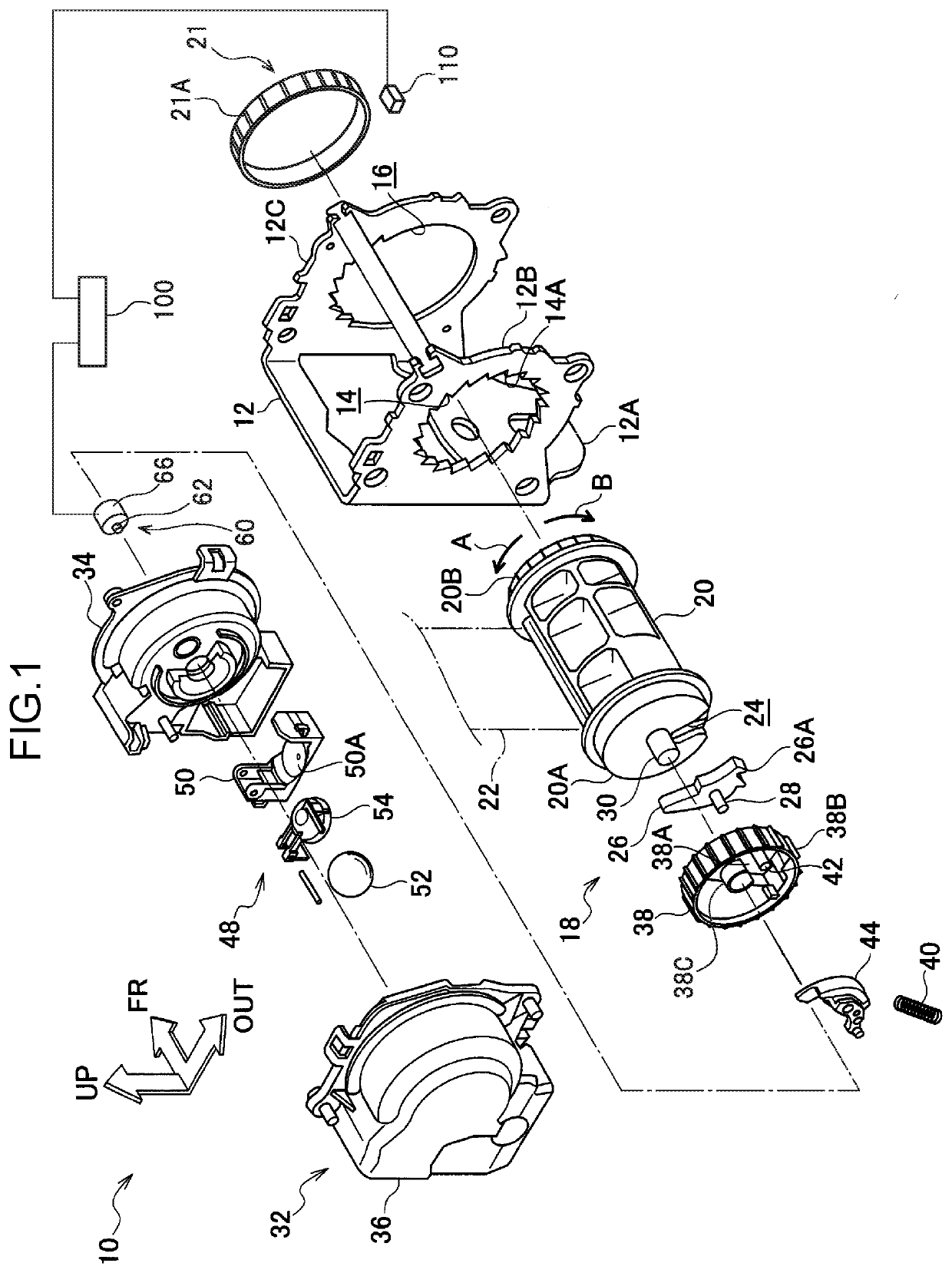
[0035]A webbing retractor 10 relating to a first embodiment of the present disclosure is shown in FIG. 1 in an exploded perspective view that is seen obliquely from a rear side, outer side and upper side. Note that, in the drawings, the vehicle front side in the state in which the webbing retractor 10 is mounted to a vehicle is indicated by arrow FR, the vehicle transverse direction outer side is indicated by arrow OUT, and the vehicle upper side is indicated by arrow UP. Further, when merely longitudinal and vertical directions are used in the following description, they refer to the longitudinal of the vehicle longitudinal direction and the vertical of the vehicle vertical direction.

[0036]As shown in FIG. 1, the webbing retractor 10 of the present embodiment has a frame 12 that is formed in a substantial U-shape as seen from the vehicle upper side. The frame 12 has a back plate 12A that extends in the vehicle vertical direction with the vehicle transverse direction being the thick...

second embodiment

Modified Example of Second Embodiment

[0086]As a modified example of the present embodiment, at the control device 100, at least one of the acceleration threshold value and the jerk threshold value may be changed in a stepwise manner, instead of correcting the acceleration of the webbing 22 based on the rotational angle. In this case, the acceleration threshold value and the jerk threshold value can be changed in accordance with the rotational angle, by using a correction table such as that described above. In accordance with the webbing retractor 10 of the present embodiment, the locking mechanism 18 can be operated accurately by correcting the threshold value, which is the object of comparison with the acceleration, instead of correcting the acceleration.

[0087]Note that, in the modified example of the present embodiment, both the acceleration threshold value and the jerk threshold value may be corrected, or either of the acceleration threshold value and the jerk threshold value may...

third embodiment

[0088]The webbing retractor 10 of the third embodiment uses a pulled-out amount sensor, which senses the pulled-out amount of the webbing 22, in controlling the locking mechanism 18. As shown in FIG. 9, in the present embodiment, a pulled-out amount sensor 120 is disposed on the path of the webbing 22, such as at the upper portion of the frame 12 or the like. A laser displacement gauge for example can be used as the pulled-out amount sensor 120. The pulled-out amount sensor 120 of the present embodiment is electrically connected to the control device 100. The control device 100 computes and acquires the acceleration of the webbing 22 from the pulled-out amount of the webbing 22 that is acquired by the pulled-out amount sensor 120. Note that, in the present embodiment, the sensor that provides input to the control device 100 is changed from the rotational angle sensor 110 of the first embodiment to the pulled-out amount sensor 120, but the other structures and the method of control b...


PUM


Abstract

A webbing retractor including: a take-up shaft that can take-up a webbing that is applied to a passenger, that takes-up the webbing by being rotated in a take-up direction, and that is rotated in a pull-out direction due to the webbing being pulled-out; a restricting member that, by being operated, restricts rotation of the take-up shaft in the pull-out direction; a driving portion that, by being electrically driven, changes an operating state of the restricting member; and a control section that acquires an acceleration of any of the webbing, the passenger or a vehicle, that computes jerk related to the acceleration, and that controls the driving portion such that the restricting member operates in a case in which the acceleration exceeds a first threshold value and the jerk exceeds a second threshold value.

Description

CROSS-REFERENCE TO RELATED APPLICATION[0001]This application is based on and claims priority under 35 USC 119 from Japanese Patent Application No. 2018-224240 filed on Nov. 29, 2018, the disclosure of which is incorporated by reference herein.BACKGROUNDTechnical Field[0002]The present disclosure relates to a webbing retractor that takes-up a webbing that is applied to a passenger.Related Art[0003]Japanese Patent Application Laid-Open (JP-A) No. 2002-234417 discloses a webbing retractor having a locking mechanism that limits pulling-out of a webbing at the time of an emergency. This locking mechanism is driven by electrical means such as a motor or a solenoid or the like, based on a collision prediction signal from a collision predicting device. Further, in JP-A No. 2002-234417, acceleration of the vehicle is given as an example of a physical amount that is made to be the sensing condition of the collision predicting device.[0004]The collision predicting device, at which acceleration...

Claims


Application Information

Patent Timeline
IPC IPC(8): B60R22/343B60R22/405B60R22/415B60W40/08
CPCB60R22/343B60R22/405B60R22/415B60W40/08B60R2022/4666
Inventor OWAKI, TOMOYASAITO, TAKUHIROYAMADA, KAZUHIRO
Owner KK TOKAI RIKA DENKI SEISAKUSHO
Why Eureka
Try Eureka