Vehicle weight measurement device

a technology of vehicle weight and measurement device, which is applied in the direction of measurement device, weighing apparatus using fluid action balancing, instruments, etc., can solve the problems of deteriorating motion performance, overloading, and illegal overloading of vehicles traveling on roads with exceeding legal load capacity, and achieves the effect of easy assembly and not disassembly

Inactive Publication Date: 2020-06-04
NSK LTD
View PDF0 Cites 1 Cited by
  • Summary
  • Abstract
  • Description
  • Claims
  • Application Information

AI Technical Summary

Benefits of technology

The patent describes a weight measurement device that can be easily installed in a vehicle and prevents relative rotation with the suspension device. The device is also designed to prevent wear and tear on the piston and sensor body, and to not disassemble without a load.

Problems solved by technology

In an automobile, particularly, a commercial vehicle such as a truck and a van for transporting a variety of goods, an illegal overloaded vehicle which travels on a road with exceeding legal load capacity becomes a social issue.
(1) The overloading may deteriorate motion performance of the automobile and damage constitutional components, which may cause an accident.
That is, the overloading involves many causes of an accident.
For example, an axle (hub) is broken, a tire is damaged (burst), a braking distance increases, a brake is overheated and poorly operates, and a vehicle is likely to overturn.
(2) The overloading causes severe damage to the road, and therefore, maintenance cost of the road increases.
There are several causes to make it difficult to prevent the overloading.
One of them is that a driver, a passenger and the like cannot easily recognize the loaded weight.
However, the installation of the platform scale requires a large facility and a large installation space, so that the installation cost increases.
Therefore, the number of platform scales which can be installed is limited, so that it is physically difficult to measure many vehicles.

Method used


Image

  • Vehicle weight measurement device
  • Vehicle weight measurement device
  • Vehicle weight measurement device

Examples


first embodiment

[0092]In the first embodiment, for example, as shown in FIG. 7, an example which is applied to a suspension device (suspension) 1 for a rear wheel of a trailing arm type for an automobile is shown. In the trailing arm type, an arm (suspension arm) 2 is pivotally supported at a right angle to a vehicle body center line (see the dashed line in the drawing) from a suspension member 3 (a constitutional component of a suspension device 1) extended across the right and left at a lower side of the vehicle and is configured to swing in an upper-lower direction at a rear side (the side of the arrow in the drawing) of the suspension member 3.

[0093]A coil spring 5 is provided on an upper surface 2a of the arm 2 via a vehicle weight measurement device 100 of the present invention. The coil spring 5 is sandwiched between the arm 2 and a lower surface of the vehicle body.

[0094]The suspension device 1 shown in FIG. 7 is configured as a known trailing arm type suspension device 1 except that the ve...

second embodiment

[0164]FIGS. 8 to 10 illustrate a second embodiment of the present invention.

[0165]A vehicle weight measurement device according to a second embodiment of the present invention applied to a suspension device for a front wheel.

[0166]The vehicle weight measurement device of the second embodiment includes: a top plate (sensor body) 7 having an upper surface side mounted to a vehicle body (vehicle) side and a lower surface side provided with an opening groove portion 9c; a diaphragm 11 configured to cover an opening area 9d of the groove portion 9c to form, together with the groove portion 9c, an oil chamber 9 of a predetermined space having a predetermined measurement fluid R filled therein; an annular collar 35 having a diameter larger than the outer diameter of the opening area 9d of the groove portion 9c and configured to sandwich and tightly fix an outer diameter side surface portion of the diaphragm 11 between the collar 35 and a surface portion outside the opening area 9d of the g...

third embodiment

[0224]FIGS. 11 to 13 illustrate a third embodiment of the present invention.

[0225]The third embodiment is different from the second embodiment in the relative-rotation preventing structure 80. Since other configurations and effects are the same as the second embodiment, the detail descriptions thereof are omitted. The bearing unit 50 is schematically shown in FIG. 11 and may have the same configuration as that of the second embodiment.

[0226]In the third embodiment, the relative-rotation preventing structure 80 includes a cutout portion 80d provided on the stopper ring 49, and protrusions 80e, 80f provided on the first piston 43 and the second piston 44.

[0227]The cutout portion 80d is formed in a circular arc shape in the plan view radially outward at a predetermined position on an inner peripheral surface of the stopper ring 49 and is continuously recessed in the vertical direction in a penetrating manner (see FIGS. 11 to 13).

[0228]The protrusions 80e, 80f are circular arc-shaped pr...


PUM


Abstract

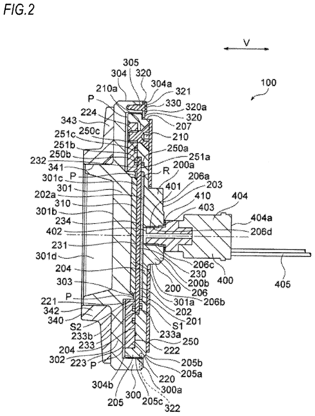
The vehicle weight measurement device includes a bottom plate in contact with an arm of a suspension device, a piston which presses a diaphragm configuring an oil chamber on an upper surface side of the bottom plate, and a pressure sensor which detects pressure of a measurement fluid in the oil chamber on an lower surface side of the bottom plate. The bottom plate includes a rotation-preventing mechanism with respect to the arm of the suspension device around the pressure sensor. A hanging circumferential edge portion is formed in a flange portion of the piston. A gap is interposed between the flange portion and the bottom plate. A protruding portion of the piston engaged in a cutout of a stopper ring and a protruding portion protruding to an upper surface side and engaged to the cutout so as to be movable in a longitudinal direction are provided.

Description

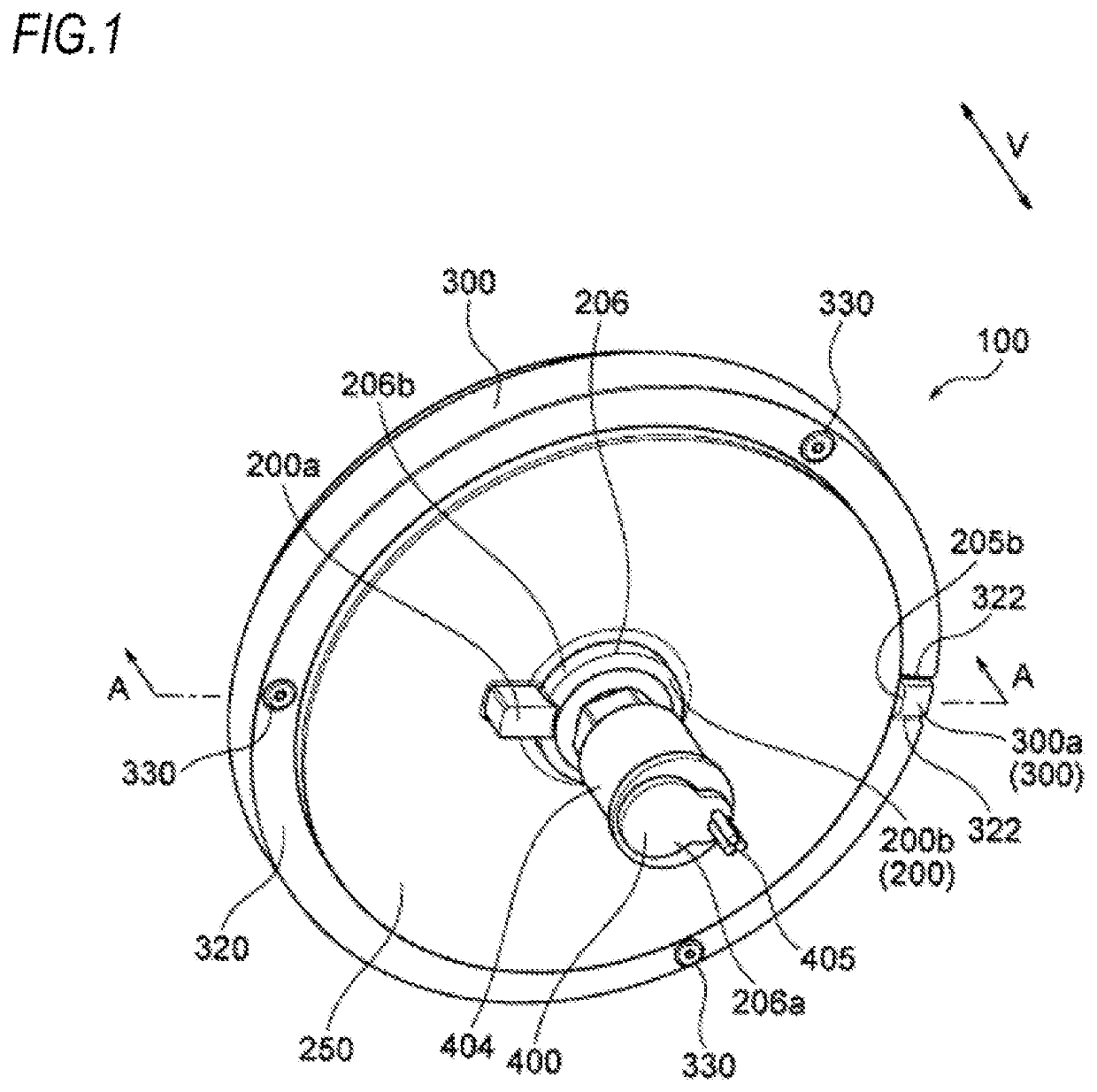
TECHNICAL FIELD[0001]The present invention relates to a vehicle weight measurement device, and particularly to, a vehicle weight measurement device to be incorporated to a suspension device of an automobile and configured to detect an overloading.BACKGROUND ART[0002]In an automobile, particularly, a commercial vehicle such as a truck and a van for transporting a variety of goods, an illegal overloaded vehicle which travels on a road with exceeding legal load capacity becomes a social issue. The reason for the overloading is that the transportation cost can be saved when carrying many goods at one time.[0003]However, the overloading should be avoided because it can cause a variety of problems, as follows.[0004](1) The overloading may deteriorate motion performance of the automobile and damage constitutional components, which may cause an accident. That is, the overloading involves many causes of an accident. For example, an axle (hub) is broken, a tire is damaged (burst), a braking d...

Claims


Application Information

Patent Timeline
Patent Type & Authority Applications(United States)
IPC IPC(8): G01G19/02G01G5/06G01G19/10
CPCG01G5/06G01G19/028G01G19/10
Inventor HIKIDA, MASAFUMIMATSUDA, YASUYUKISUZUKI, EISAKU
Owner NSK LTD
Why Eureka
Try Eureka