A pipe cleaning device

Pending Publication Date: 2020-06-11
ATAM GRP LTD
View PDF0 Cites 4 Cited by
  • Summary
  • Abstract
  • Description
  • Claims
  • Application Information

AI Technical Summary

Benefits of technology

[0043]Alternatively or additionally optionally, the spacer element includes a cage to minimise damage to the device dur

Problems solved by technology

The problem is particularly encountered when constructing a pipeline or process piping system from pipe sections, during which pipe sections are joined together, typically by welding.
However, these devices can cause various problems where oxidation and corrosion from water left in the pipes has caused damage to the pipes, resulting in expensive costs of running and environmental issues as

Method used


Image

  • A pipe cleaning device
  • A pipe cleaning device
  • A pipe cleaning device

Examples


first embodiment

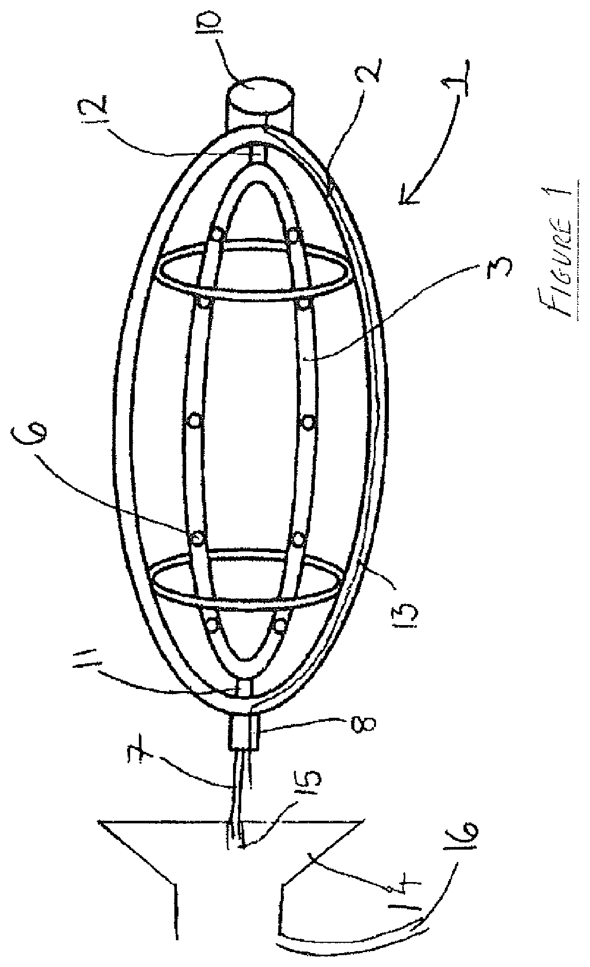
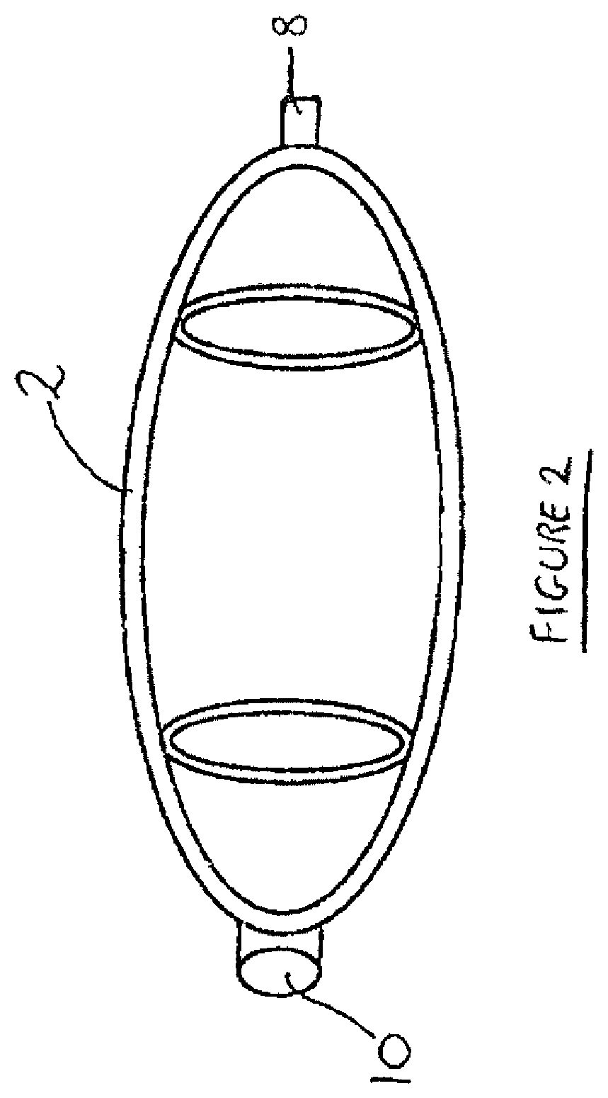
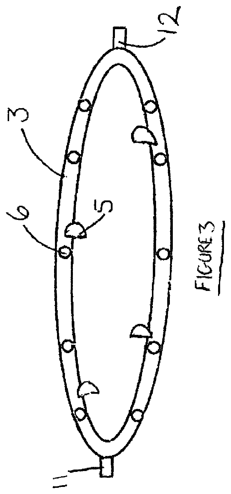
[0053]FIG. 1 shows a side view of a cleaning device 1. This view shows both the outer frame 2 and a conduit 3 mounted for rotation to the frame of the device 1. In a preferred embodiment the conduit 3 is in the form of a ring, as shown and in a further preferred embodiment the ring of the conduit 3 is formed in an elliptical shape. The elliptical ring shape of the rotatable conduit 3 allows for efficient rotation as well as efficient travel of the device 1 into a pipe due to the streamlined shape. However, it is envisioned that that the conduit may be any suitable shape.

[0054]In a preferred embodiment the air enters the conduit ring via an inlet at the in-use rear end of the conduit 3. Air can be supplied from an external compressed air supply (not shown). FIG. 1 shows an air supply hose 7 which attaches to the device via a threaded hose connection 8.

[0055]The conduit 3 is capable of rotating at various speeds, the speed of rotation dependent on the pressure of the air supplied.

[005...

fourth embodiment

[0085]Referring to FIG. 7, this shows a device 70. The device 70 has a centraliser frame 71 supporting an air manifold 72 and a camera support 73. The centraliser frame 71 is formed of a plurality of tubular members 74a-c, secured together typically by means of a welded seam or other means known in the art. At the in-use front end of the device 70, is mounted a camera 75 connected to a cable 76, allowing images from within the pipework being cleaned to be obtained and transmitted. The air manifold 72 comprises rearward facing sections 77, having at their free ends 77a an air jet or nozzle 78. In order to receive compressed air into the manifold, an air hose connection 79 is provided. Additionally, a connector 80 to receive a pushrod is provided, to facilitate movement of the device in and out of the pipe or spool work.

[0086]The device as herein described allows a considerable amount of time and costs to be saved the construction of a clean piping system in that it enables the system...


PUM


Abstract

A device for cleaning the internal surface of a pipe has a main pipe axis. The device further includes one or more generally tubular conduits, including a conduit wall, at least one of the or each tubular conduit including an inlet to receive pressurised gas into the tubular conduit. One or more nozzles is deployed around the outside of the or each tubular conduit, with the or each nozzle being in fluid connection with the tubular conduit. At least one nozzle is directed at least partially to direct fluid in a direction non-perpendicular to the main tubular conduit axis, with one or more spacer elements to hold the or each tubular conduit in spaced relationship to a pipe.

Description

FIELD OF THE INVENTION[0001]The invention relates to a device to dewater or clean the internal surface of a pipe or the like. The device acts to dry or to urge water dust, debris and the like out of the pipe or a piping system.BACKGROUND TO THE INVENTION[0002]Pipes of all sizes and uses, including pipes for gas and also pipes for liquids, which pipes are, often, as particularly contemplated in the current invention, located above ground, encounter difficulties with cleanliness due to build up of debris within the pipes in areas which are hard to reach due to the length of the pipes. The problem is particularly encountered when constructing a pipeline or process piping system from pipe sections, during which pipe sections are joined together, typically by welding. Debris either from the joining process, left behind by an operative or simply blown in from the outside environment can accumulate within the pipeline.[0003]Existing cleaning and inspection methods include using water jets ...

Claims


Application Information

Patent Timeline
IPC IPC(8): B08B9/043B08B9/049E03F9/00
CPCB08B9/0433E03F9/002B08B9/0495B08B2209/04
Inventor LOADES, MARK
Owner ATAM GRP LTD
Why Eureka
Try Eureka