Propeller-Hub Assembly With Folding Blades For VTOL Aircraft

a technology of propeller hub and blade, which is applied in the direction of propellers, vertical landing/take-off aircraft, transportation and packaging, etc., can solve the problems of unfavorable vertical take-off, hovering or landing phases of flight, and the propeller is not practical to use in vertical take-off, hovering or landing phases of flight, and achieves the effect of expanding the blade position

Inactive Publication Date: 2020-06-11
KAPETER LUKA
View PDF0 Cites 10 Cited by
  • Summary
  • Abstract
  • Description
  • Claims
  • Application Information

AI Technical Summary

Benefits of technology

[0009]During the vertical flight or hover mode the rotating plate supporting the assembly is vertically oriented and perpendicular to the restraint plate. The push rod, which is firmly attached to the bedplate is passing through the propeller-hub, the motor and the rotating plate. In this flying mode, the push rod is not pushed by the restraint plate in which position the spring is not compressed, thus enabling expanded position of the blades. Furthermore, when the rotating plate is vertically oriented and perpendicular to the restraint plate, the blades are always in the expanded position irrespective if the motor is running or not, thus enabling starting of the motor for vertical take-off with blades being in expanded position.

Problems solved by technology

Standard fixed pitch un-foldable propellers have a downside of generating too much drag if they are turned off during the forward progressing flight which is required by some versions of VTOL aircraft's.
However, such a propeller is not practical to use in the vertical take-off, hover or landing phases of flight, because it requires the propeller to be started in the horizontal flight mode.
Both folding and unfolding propellers can be used in the VTOL configuration, but as explained above, none of them is fulfilling all of the requirements.

Method used


Image

  • Propeller-Hub Assembly With Folding Blades For VTOL Aircraft
  • Propeller-Hub Assembly With Folding Blades For VTOL Aircraft
  • Propeller-Hub Assembly With Folding Blades For VTOL Aircraft

Examples


Embodiment Construction

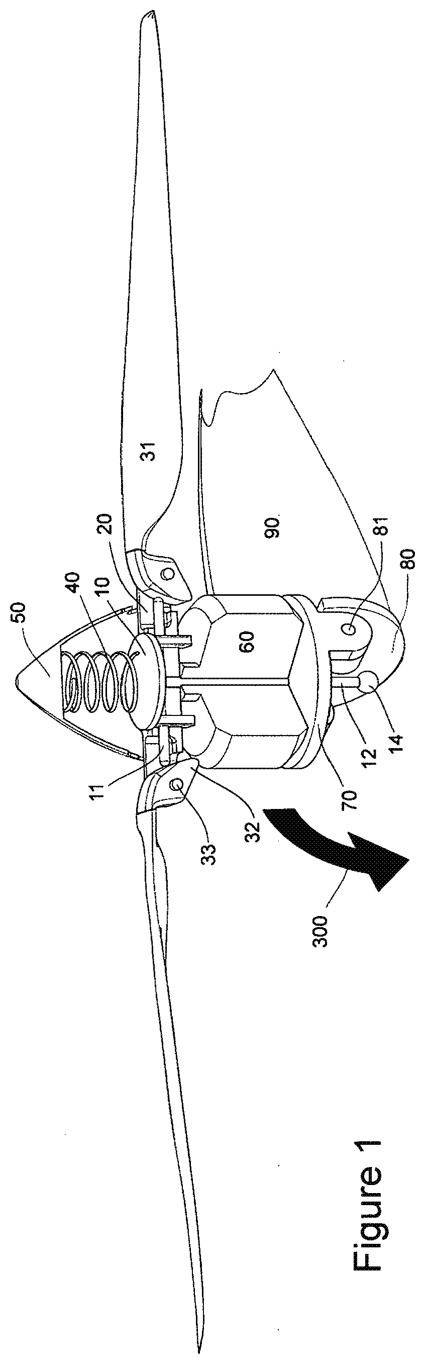
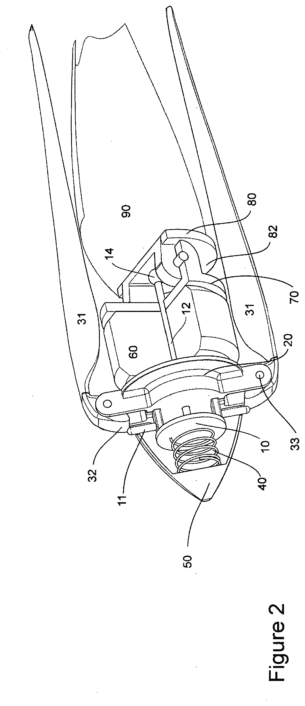
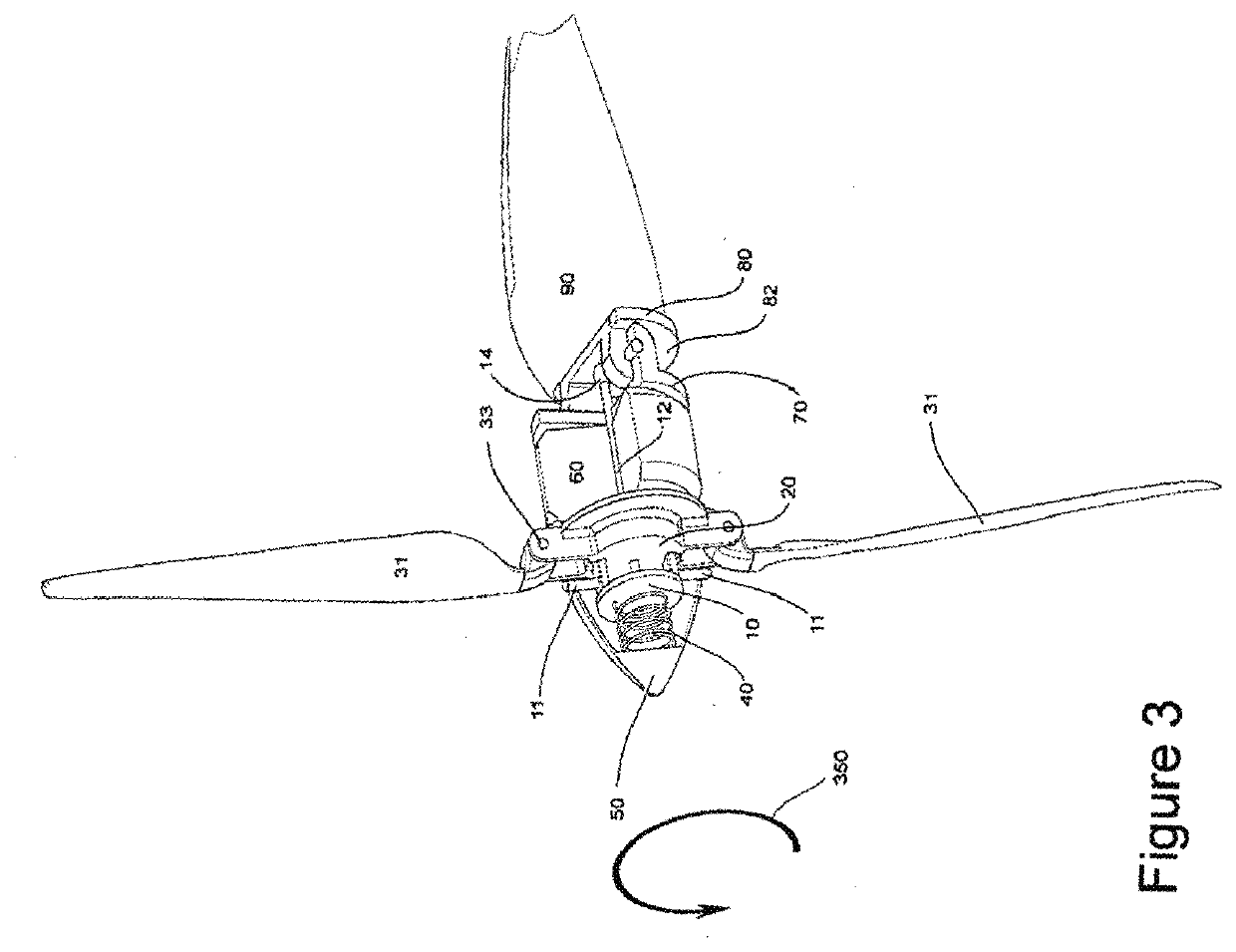
[0028]Illustrative embodiments of the assembly of the present application are described below. The use of terms such as “above,”“below,”“upper,”“lower,” or other like terms to describe a spatial relationship between various components or to describe the spatial orientation of aspects of such components should be understood to describe a relative relationship between the components or a spatial orientation of aspects of such components, respectively, as the assembly described herein may be oriented in any desired direction. Furthermore, as described herein, the substantially vertical orientation and the substantially horizontal orientation of the propeller-hub assembly are defined with respect to the orientation of the axis of the propeller rotation relative to the surface of the Earth. It must be noted that as used herein and in the appended claims, the singular forms “a”, “an”, and “the” include plural referents unless the context clearly dictates otherwise. The present application...


PUM


Abstract

A folding propeller-hub assembly for VTOL aircraft provides two modes of operation, a vertical mode with unfolded propeller blades and a horizontal mode with propeller blades positionable in both an aerodynamic folded position and an active unfolded position. The propeller-hub assembly includes a plurality of propeller blades, a bedplate operably associated with a propeller-hub to fold or respectively unfold the propeller blades, the motor arranged between the propeller-hub and a rotating plate, a push rod positioned in the axis of the propeller rotation along the propeller-hub assembly. The bedplate is operably associated with a device which connects with the spinner bottom of the spinner to rotate the propeller blades. A restraint plate by virtue of the push rod is operably associated with the propeller blades to rotate each propeller blade about a propeller blade pin axis.

Description

FIELD OF INVENTION[0001]The present invention relates in general to the field of vertical take-off and landing (VTOL) aircraft. In particular, the present invention relates to a propeller-hub assembly used for the VTOL aircrafts or VTOL UAV or VTOL aircraft models whose propeller blades are folding during flight and to the multi flight modes being enabled by said assembly.DESCRIPTION OF THE BACKGROUND ART[0002]VTOL aircraft have two specific flight phases: vertical take-off, hover and landing and horizontal forward flight. Transition between the vertical to the horizontal flight is referred to as outbound, whereas the transition between the horizontal and vertical flight is referred to as inbound transition. To be able to switch between different phases of flight it is required to either rotate the propellers (rotors) or to rotate the whole wing carrying propellers (rotors). Tiltrotor aircraft are hybrids between traditional helicopters and traditional propeller driven aircraft. Typ...

Claims


Application Information

Patent Timeline
Patent Type & Authority Applications(United States)
IPC IPC(8): B64C27/50B64C29/00B64C39/02
CPCB64C29/0033B64C2201/108B64C2201/02B64C2201/042B64C2201/141B64C27/50B64C39/024B64C11/28B64C11/04B64U10/00B64U30/20B64U50/19B64U2201/10
Inventor KAPETER, LUKA
Owner KAPETER LUKA
Why Eureka
Try Eureka