
Tethered payload motion control and cable robot using magnetorheological actuators

a technology of magnetorheological actuators and motion control, which is applied in the direction of emergency apparatus, hoisting equipment, launching weapons, etc., can solve the problems of large detrimental payload motion, limited maximum velocity at which the payload can be towed, and the payload remains sensitive to wind gusts

Pending Publication Date: 2020-06-11
SCOPRA SCI & GENIE SEC +1
View PDF0 Cites 4 Cited by
  • Summary
  • Abstract
  • Description
  • Claims
  • Application Information

AI Technical Summary

Benefits of technology

The present disclosure aims to provide a new system and method for controlling the tension of a tether between an object and a load that is attached to the object. This allows for better control and management of the load, improving efficiency and safety.

Problems solved by technology

However, the maximum velocity at which the payload can be towed is limited by the dynamic motion of the payload due to unsteady aerodynamics on the bluff body.
However, in collaborative load lifting, the tethered aircrafts may be sensitive to wind gust, and therefore, may create large detrimental payload motion or change the load repartition between the involved aircraft.
The payload remains sensitive to wind gust since the system is typically not controlled in tension.
However, high accelerations together with inertia inherent to high-speed manipulations can affect winch position tracking performance, which, in turn, may cause tension distribution changes.
Current driving method of cable that are usually based on position tracking errors that induce tension discrepancies in the system may create payload position error.

Method used


Image

  • Tethered payload motion control and cable robot using magnetorheological actuators
  • Tethered payload motion control and cable robot using magnetorheological actuators
  • Tethered payload motion control and cable robot using magnetorheological actuators

Examples


Embodiment Construction

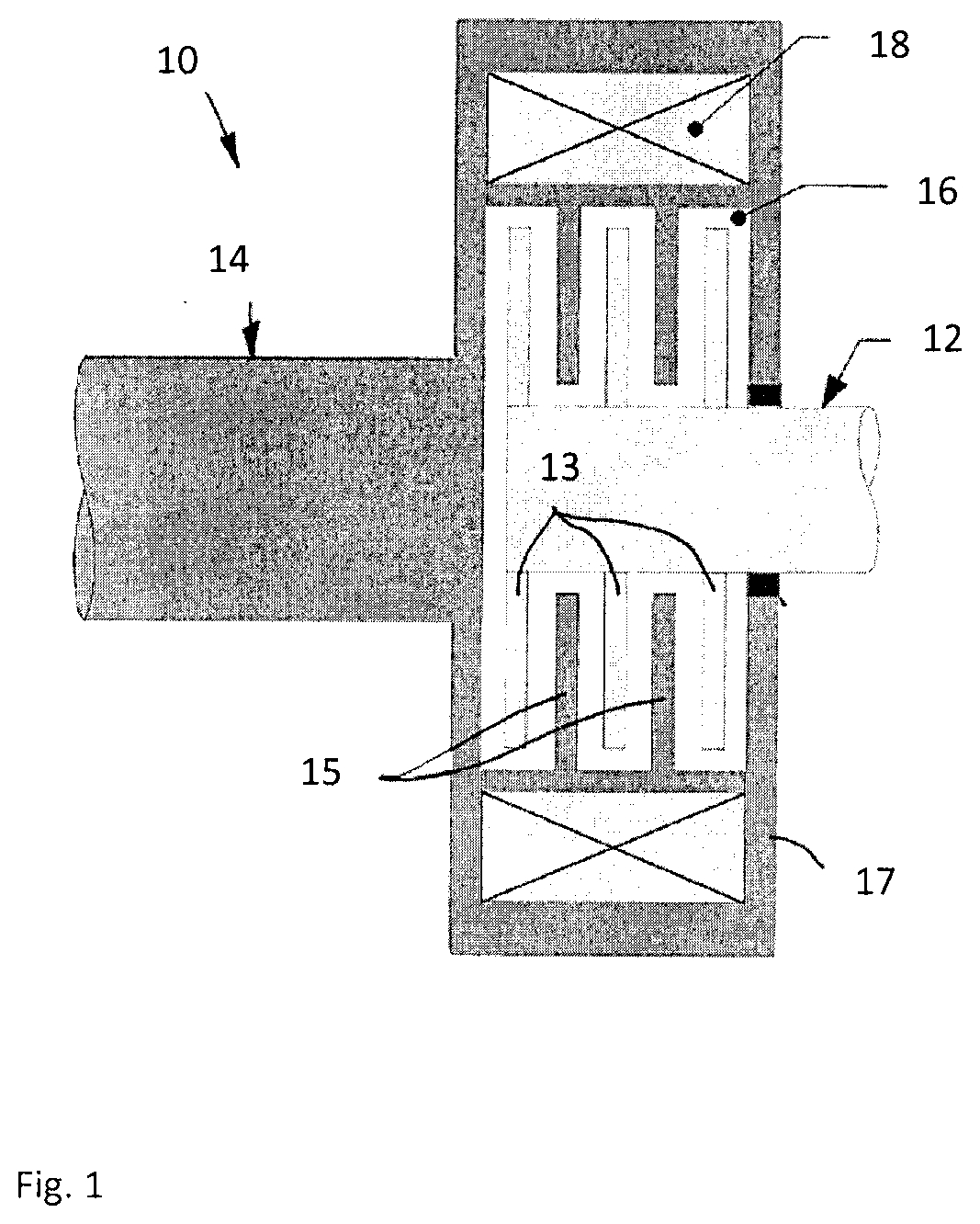
[0056]Referring to the drawings and more particularly to FIG. 1, there is illustrated a generic magnetorheological (MR) fluid clutch apparatus 10 configured to provide a mechanical output force based on a received input current. The MR fluid clutch apparatus 10 of FIG. 1 is a simplified representation of a MR fluid clutch apparatus that may be used in the systems described hereinafter. The MR fluid clutch apparatus that is used in the systems described hereinafter may have additional components and features, such as drums, redundant electromagnets, MR fluid expansion systems, etc.

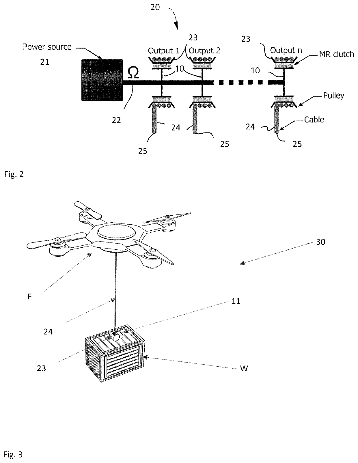
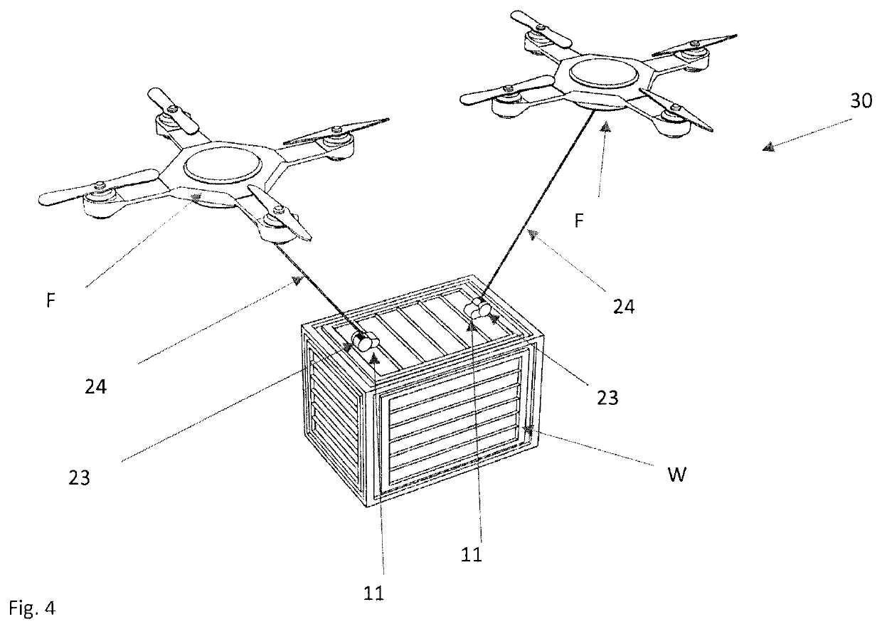
[0057]The MR fluid clutch apparatus 10 may be part of a MR fluid actuator unit 11 as shown in FIG. 10 and described in further detail hereinafter. The MR fluid clutch apparatus 10 has a driving member 12 with radial disks 13, this assembly also known as input rotor. The MR fluid clutch apparatus 10 also has a driven member 14 with annular plates 15 intertwined with the radial disks 13 to define an annular c...


PUM


Abstract

A system for controlling a tension of a tether between an object and a load tethered to the object comprises magnetorheological (MR) fluid actuator unit(s) including at least one torque source and at least one MR fluid clutch apparatus coupled to the at least one torque source to receive torque from the at least one torque source, the MR fluid clutch apparatus controllable to transmit a variable amount of torque via an output of the MR fluid actuator unit. A tensioning member is connected to the output so as to be pulled by the output member upon actuation of the magnetorheological fluid clutch apparatus, a free end of the tensioning member adapted to exert a pulling action when being pulled by the output member. Sensor(s) provide information indicative of a relation between the object and the load tethered to the object. A controller controls the at least one MR fluid clutch apparatus in exerting the pulling action based on said information.

Description

CROSS-REFERENCE TO RELATED APPLICATION[0001]The present application claims the priority of U.S. Patent Application No. 62 / 551,592, filed on Aug. 29, 2017 and of U.S. Patent Application No. 62 / 579,532, filed on Oct. 31, 2017, both of which are incorporated herein by reference.FIELD OF THE APPLICATION[0002]The present application relates generally to magnetorheological (MR) fluid clutch apparatuses, to cable-driven systems and more particularly to a dynamic motion control of a tethered payload using such apparatuses.BACKGROUND OF THE ART[0003]Payload lifting using aircraft have been used for decades. For example, slung loads under helicopters are extensively used to deliver payloads in difficulty accessible areas, in collaborative load lifting using aircraft (e.g., quadcopters used to lift particularly heavy or voluminous loads). Fixed-wing aircraft and aerostats are also used to lift payloads. Recently, drones have been extensively used to lift various payload, including camera equip...

Claims


Application Information

Patent Timeline
Patent Type & Authority Applications(United States)
IPC IPC(8): F16D37/02B64C39/02B64D1/22B66C13/08B66D1/14F16D48/06
CPCF16D2500/10475F16D48/06B64D1/22F16D2037/004B66C13/085F16D37/02B66D1/14B64C39/024B64C2201/128F16D2500/3027B66F19/00B64D1/12B64D17/22B64U70/30B64U10/14B64U2101/67B64U2101/64
Inventor RANCOURT, DAVIDLUSSIER DESBIENS, ALEXISPLANTE, JEAN-SEBASTIENLAROSE, PASCAL
Owner SCOPRA SCI & GENIE SEC
Learn More