
Gas Injector

a gas injector and gas technology, applied in the direction of fuel supply apparatus, internal combustion piston engines, engine components, etc., can solve the problems of affecting reliable switching, affecting and affecting the reliability of switching, so as to achieve the effect of increasing the service life of gas injectors

Active Publication Date: 2020-06-18
EUGEN SEITZ
View PDF0 Cites 2 Cited by
  • Summary
  • Abstract
  • Description
  • Claims
  • Application Information

AI Technical Summary

Benefits of technology

The patent text describes an injector lance valve design that prevents delays caused by compressible gases and minimizes unburned hydrocarbons. The valve opening is located at the outermost region of the injector lance, preventing the formation of dead spaces. This also allows the combustion reaction or flame front to progress directly to the valve, increasing combustion efficiency. Additionally, the spring force and valve stroke can be adjusted individually for each gas injector, allowing for precise customization to meet different customer requirements. Overall, this design improves engine performance and fuel efficiency.

Problems solved by technology

Intervening spaces are thus created, which result in switching delays owing to the compressibility of the gas.
Moreover, these gas injectors become contaminated relatively quickly.
However, deposits in the valve region can interfere with reliable switching.
In particular, sooting in the region of the valve seat can cause functional problems in the internal combustion engines.
This arrangement is disadvantageous in that the Venturi nozzle or the de Laval nozzle creates a dead space in which soot deposits and unburned hydrocarbons are produced.
US 2011 / 0214639 discloses a switching valve and a metering valve having a corresponding intervening space, which results in switching delays.

Method used


Image

  • Gas Injector
  • Gas Injector
  • Gas Injector

Examples


Embodiment Construction

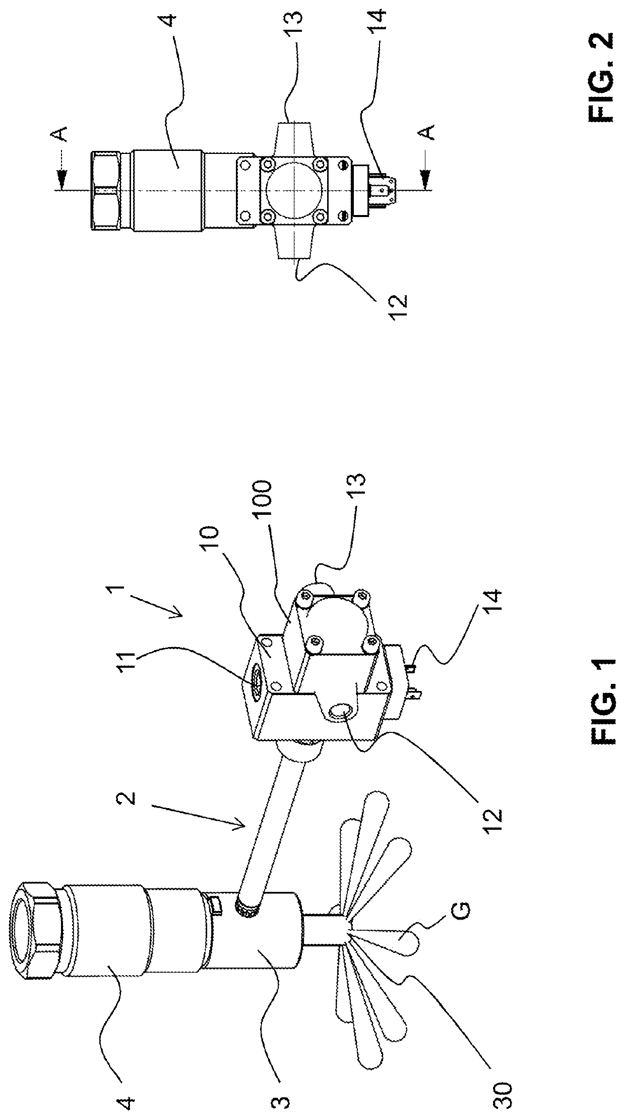
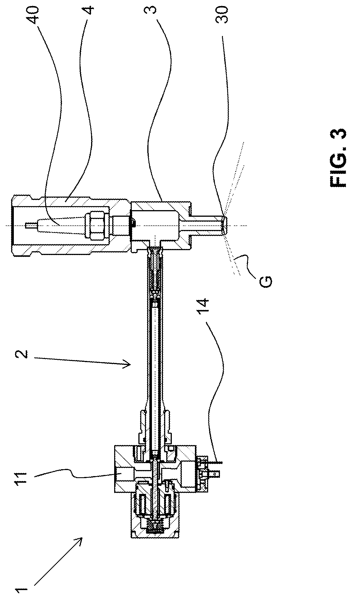
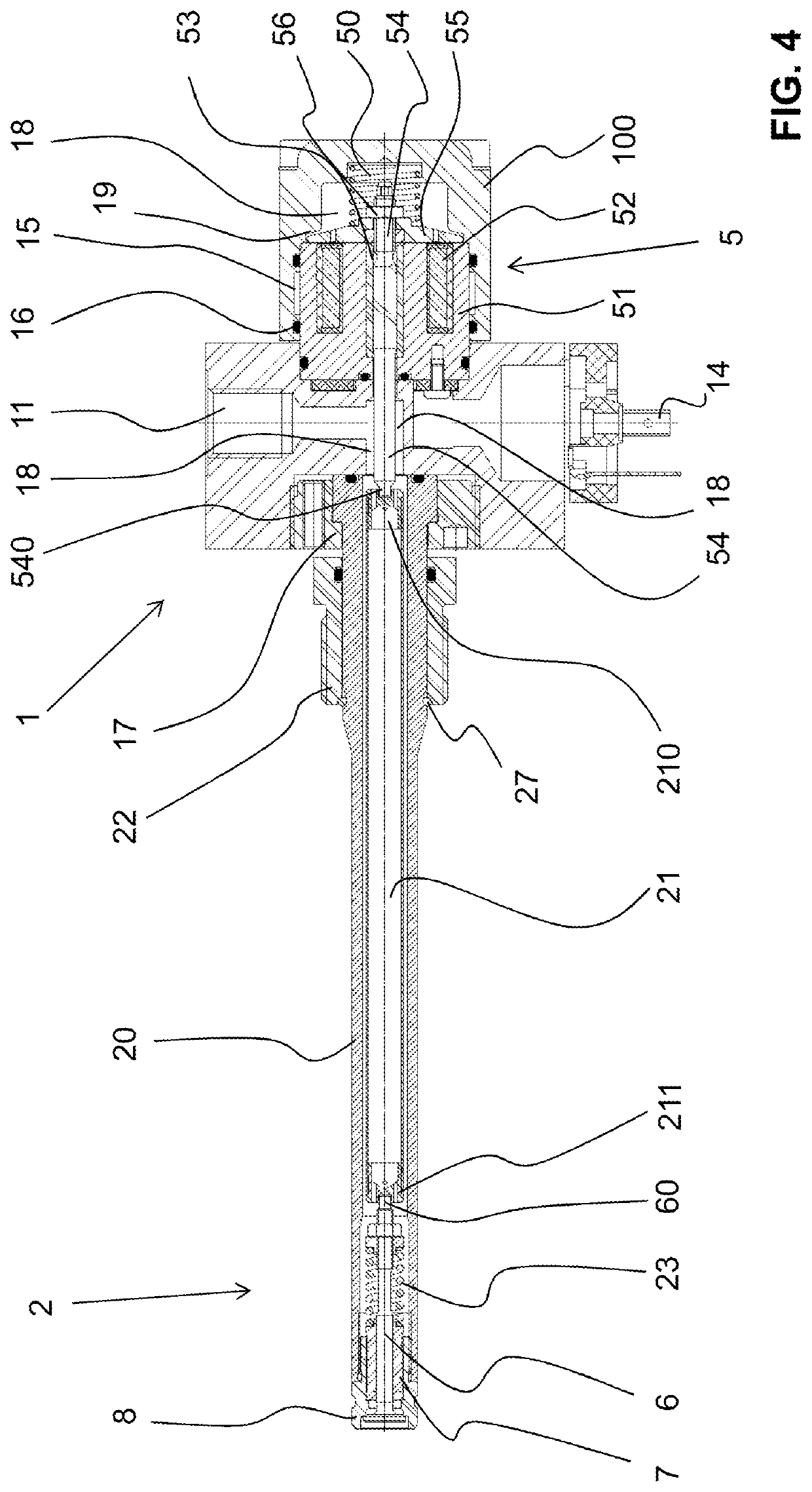
[0058]A gas injector according to the invention is illustrated in an exemplary application in FIGS. 1 to 3.

[0059]The gas injector has a base unit 1 and an injector lance 2. The base unit 1 has a base housing 10, which is tightly closed by a cover 100. A gas connection 11 is present on one side of the base housing 10 and an electrical plug 14 is arranged on an opposite side. A coolant inlet 12 and a coolant outlet 13 are located in the cover 100.

[0060]Instead of the plug 14, an electrical connection can also be securely connected to the housing. This is then particularly advantageous if the gas injector is to be used at high environmental temperatures.

[0061]As an alternative to the shown gas connection 11 of the base unit, the injector lance 2, more precisely the shaft 20 described below, can be provided with a bore or with a plurality of bores for the introduction of gas. In this case, a hollow pressure screw is preferably used in order to ensure a combustion-gas seal between the in...


PUM


Abstract

After the claims, please insert a page containing the Abstract of the Disclosure which is attached hereto as a separately typed page.

Description

TECHNICAL FIELD[0001]The present invention relates to a gas injector, in particular for an internal combustion engine.PRIOR ART[0002]The gas injector, also known as an injection valve, meters gas, for example, into a prechamber or a into combustion chamber of an internal combustion engine, in particular a gas engine. In machines, a non-return valve can also be connected downstream in order to enable gas to be injected in a metered manner. The gas injector is conventionally electromagnetically operated, preferably by means of a solenoid.[0003]Two valves are required for metering purposes—a switching valve and a non-return valve—or a nozzle, which conducts the gas to the combustion point, is connected downstream of the switching valve. Intervening spaces are thus created, which result in switching delays owing to the compressibility of the gas. Moreover, these gas injectors become contaminated relatively quickly. However, deposits in the valve region can interfere with reliable switch...

Claims


Application Information

Patent Timeline
Patent Type & Authority Applications(United States)
IPC IPC(8): F02M21/02F02B19/00
CPCF02M21/0254F02B19/00F02M21/0269F02M21/0215F02M21/0296Y02T10/30
Inventor BRONNER, MICHAEL
Owner EUGEN SEITZ
Learn More