Unlock instant, AI-driven research and patent intelligence for your innovation.

Coil

a coil and coil technology, applied in the field of coils, can solve the problems of increasing the ac resistance of the conductor, affecting the current distribution of a single wire, and affecting the distribution of current within a single wire,

Pending Publication Date: 2020-06-18
COMSYS
View PDF5 Cites 0 Cited by
  • Summary
  • Abstract
  • Description
  • Claims
  • Application Information

AI Technical Summary

Benefits of technology

The patent describes a coil design that uses a multi-part conductor to distribute current more effectively and decrease the maximum current density. The position of the conductors changes as a result of winding the coil, which leads to a weaker proximity effect and a lower overall resistance of the coil. The two or more conductors are affected by eddy currents to a similar degree, which results in similar AC resistance and current in each conductor when connected in parallel to an AC source. The coil may also include an electrically insulating element to increase the resonance frequency of the coil. The two or more conductors have a substantially rectangular cross section, and the conductors are arranged perpendicular to the central axis to minimize proximity effects. The multi-part conductor may consist of two conductors, each at an edge of the coil, to efficiently reduce resistance due to the proximity effect.

Problems solved by technology

Furthermore, induced eddy currents due to alternating currents also affect the distribution of current within a single wire.
The increased AC resistance in the conductor due to the proximity and skin effects may for high energy alternating current applications become a significant problem.
One disadvantage is that a higher resistance will introduce unwanted power losses in the system.
This will in turn generate unwanted heat within the conductor and thus increase the temperature of the system.
Furthermore, it will make the coil less efficient.
A part of a conductor located within the coil, along the direction of the central axis, will be subjected to a weaker proximity effect as the magnetic fields generated by adjacent conductors on both sides will partly add destructively to the magnetic field inside the part of the conductor located within the coil.

Method used


Image

  • Coil
  • Coil
  • Coil

Examples


Embodiment Construction

[0029]The present invention will now be described more fully hereinafter with reference to the accompanying drawings, in which currently preferred embodiments of the invention are shown. This invention may, however, be embodied in many different forms and should not be construed as limited to the embodiments set forth herein; rather, these embodiments are provided for thoroughness and completeness, and fully convey the scope of the invention to the skilled person.

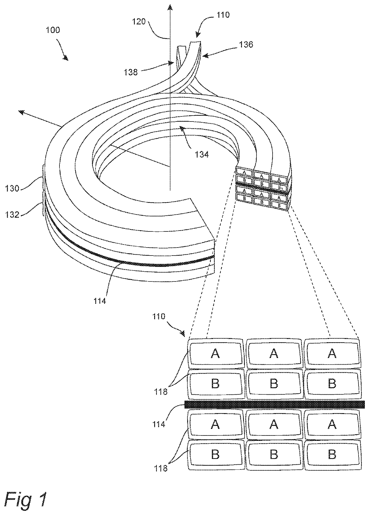
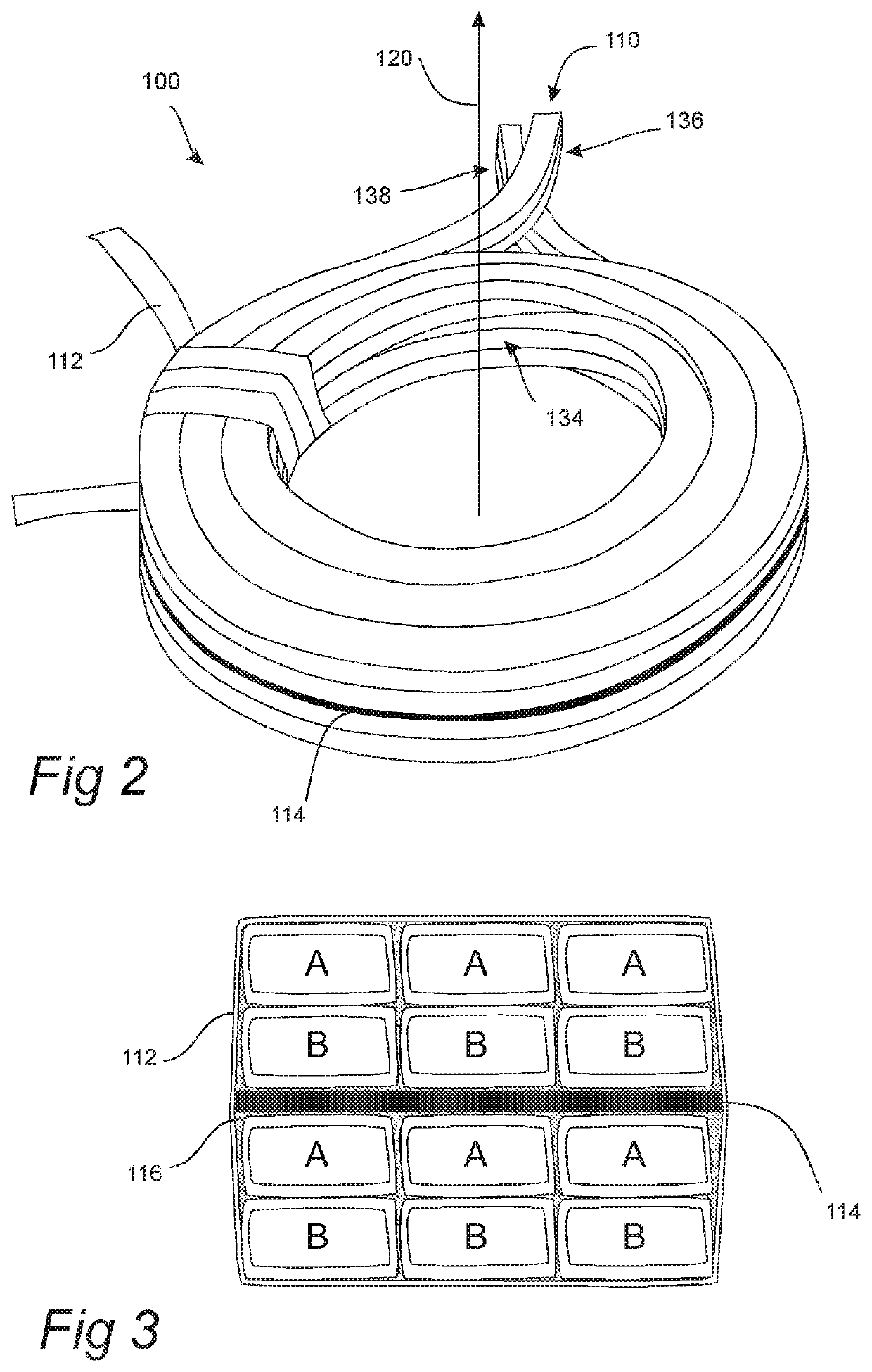
[0030]FIG. 1 shows a coil 100 comprising a multi-part conductor 110. The coil 100 is intended for high alternating current applications such as active filters, etc. The multi-part conductor 110 comprises two conductors A,B being electrically insulated from its surroundings and each other by an electrically insulating layer of varnish 118. The varnish layer 118 is very thin and only about 20 μm thick. The two conductors A,B are arranged adjacent to each other in the direction of a central axis 120 of the coil 100. The multi-...


PUM

PropertyMeasurementUnit
thickaaaaaaaaaa
distanceaaaaaaaaaa
electrically insulatingaaaaaaaaaa

Abstract

The disclosure relates to a coil (100) comprising: a multi-part conductor (110) having a long extension (in relation to its cross-section), the multi-part conductor comprising two or more conductors (A,B) being electrically insulated from each other, wherein, in a cross-section of the multi-part conductor (110), at least two of said two or more conductors (A,B) are arranged adjacent to each other in the direction of the central axis (120), wherein said multi-part conductor (110) is wound around the central axis (120) in more than one circumferential turn, such that a first portion (130) of the multi-part conductor (110) is arranged adjacent to a second portion (132) of the multi-part conductor (110) in the direction of the central axis (120), and wherein said adjacent arrangement of said two or more conductors (A,B) is the same in relation to each other and in relation to the direction of a central axis (120) of the coil (100) for each circumferential turn.

Description

FIELD OF THE INVENTION[0001]The present disclosure relates to a coil. More specifically, the disclosure relates to an electromagnetic coil.BACKGROUND ART[0002]Electromagnetic coils are electrical conductors such as a wire in the shape of a coil, spiral or helix. Electromagnetic coils are used in electrical engineering, in applications where electric currents interact with magnetic fields, in devices such as inductors, electromagnets, transformers, and sensor coils.[0003]For applications requiring relatively large alternating currents, i.e. chokes for active frontend output filters, dU / dt chokes for output filters for drives, grid side chokes for active harmonic filters, large time-varying magnetic fields will be present. Such magnetic fields will influence the distribution of an electric current flowing within an electrical conductor, by electromagnetic induction. The alternating magnetic field induces eddy currents in adjacent conductors, affecting the distribution of current flowi...

Claims


Application Information

Patent Timeline
Patent Type & Authority Applications(United States)
IPC IPC(8): H01F27/28H01F27/32H01F5/06
CPCH01F27/327H01F27/323H01F27/2823H01F5/06H01F5/00
Inventor CEDELL, TORD
Owner COMSYS