Roof rack side ladder

a side ladder and rack technology, applied in the field of vehicle ladders, can solve the problems of affecting the cleaning and maintenance affecting the visibility of the rear window, and many vehicle ladder inventions in the art, so as to improve visibility, prevent theft, and facilitate installation. the effect of speed and convenien

Active Publication Date: 2020-06-25
NAKARI TIMOTHY +1
View PDF26 Cites 2 Cited by
  • Summary
  • Abstract
  • Description
  • Claims
  • Application Information

AI Technical Summary

Benefits of technology

[0007]The installment of the roof rack side ladder system to a vehicle offers several benefits over the prior art. The installment of the ladder to the side of the vehicle instead of the rear hatch is advantageous owing to improved visibility through the rear window, ease of cleaning and maintaining the rear window, and allowing a user to access the top of a vehicle while the rear lift gate, tail gate, or rear door is open. The dual-pivot attachment of the top of the ladder to the roof rack allows the rack to move up and down freely as well as twist, thereby ensuring that the ladder does not introduce an undesirable and damaging force to the roof rack or the vehicle body during normal vehicle operation. Furthermore, the dual pivot attachment of the connecting arm and the lower fastener attachment of the lower part of the ladder assembly to the bumper bracket allow for quick and convenient installation and removal of the ladder assembly, which helps prevent theft and eases removal of the ladder assembly where tight obstacles are encountered or where the clearance between the obstacle and ladder is of concern.

Problems solved by technology

Several vehicle ladder systems are known in the art; however, many vehicle ladder inventions in the art are limited and do not address the several issues that arise with ladder systems installed to the rear door or rear hatch of the vehicle, including obstruction of view through the rear window from the seat of the driver, hindrance to cleaning and maintenance of the rear window, and lack of access to the top of the vehicle while the rear door or rear hatch opened.
Furthermore, many vehicle ladder inventions in the art do not address the issue of the ladder putting force on the roof rack or vehicle while in transit nor do they provide a ladder that easily attaches and detaches onto the vehicle.

Method used


Image

  • Roof rack side ladder
  • Roof rack side ladder
  • Roof rack side ladder

Examples


Embodiment Construction

[0068]Illustrative embodiments of the invention are described below in the accompanying Figures. The following detailed description provides detailed schematics for a thorough understanding of and an enabling description for these embodiments. One having ordinary skill in the art will understand that the invention may be practiced without certain details. In other instances, well-known structures and functions have not been shown or described in detail to avoid unnecessarily obscuring the description of the embodiments. In the description, terms such as “front”, “side”, and “bottom” should be construed to refer to orientation as then described or as shown in the drawings under discussion. These terms are for convenience of description and do not require that the system or component of the system be operated in a particular orientation.

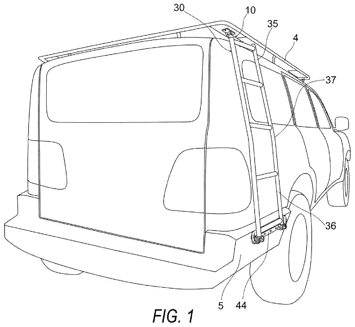
[0069]FIG. 1 is a perspective view of the roof rack side ladder system installed onto a vehicle, in accordance with an exemplary embodiment of the pre...


PUM


Abstract

A roof rack side ladder system is provided with a ladder assembly, a roof rack mounting assembly, and a bumper bracket. The roof rack mounting assembly attaches the upper ladder portion of the ladder assembly to the roof rack of a vehicle and provides for a dual pivot attachment of the ladder assembly to the roof rack for absorbing suspension forces while the vehicle is in transit. The bumper bracket attaches the lower ladder portion of the ladder assembly to the side bumper wing of a vehicle.

Description

STATEMENT REGARDING FEDERALLY SPONSORED RESEARCH AND DEVELOPMENT[0001]Not Applicable.FIELD OF THE INVENTION[0002]The present invention relates generally to vehicle ladders and relates more specifically to accessing topside vehicle storage using a ladder.BACKGROUND OF THE INVENTION[0003]Several vehicle ladder systems are known in the art; however, many vehicle ladder inventions in the art are limited and do not address the several issues that arise with ladder systems installed to the rear door or rear hatch of the vehicle, including obstruction of view through the rear window from the seat of the driver, hindrance to cleaning and maintenance of the rear window, and lack of access to the top of the vehicle while the rear door or rear hatch opened. Furthermore, many vehicle ladder inventions in the art do not address the issue of the ladder putting force on the roof rack or vehicle while in transit nor do they provide a ladder that easily attaches and detaches onto the vehicle.SUMMARY...

Claims


Application Information

Patent Timeline
Patent Type & Authority Applications(United States)
IPC IPC(8): E06C5/24B60R3/00B62D65/16
CPCE06C5/24B60R3/005B62D65/16E06C9/06E06C9/08E06C9/085
Inventor NAKARI, TIMOTHYSMITH, MICHAEL
Owner NAKARI TIMOTHY
Why Eureka
Try Eureka