Systems and methods for compression pack pipe insulation

a compression pack and pipe insulation technology, applied in the direction of thermal insulation protection of pipes, synthetic resin layered products, metal layered products, etc., can solve the problems of significantly increasing the cost and time associated with insulating pipes or vessels, generating loud noise from compression processes, etc., to achieve the effect of minimal thickness, excellent thermal and acoustic performance, and minimal thickness

Inactive Publication Date: 2020-06-25
JOHNS MANVILLE CORP
View PDF0 Cites 0 Cited by
  • Summary
  • Abstract
  • Description
  • Claims
  • Application Information

AI Technical Summary

Benefits of technology

[0004]Embodiments of the invention relate to an insulation and insulation systems for pipes, storage tanks, and vessels. The insulation and insulation systems described herein provide excellent thermal and acoustic performance with minimal thickness compared to conventional insulation solutions. The present insulations are particularly useful for applications involving cryogenic liquid storage tanks and other storage containers that store liquids below 300° F. where insulation thickness needs to be minimized. The insulations may also be used in applications that utilize traditional cryogenic insulation, such as cellular glass or PIR foam, but that also require acoustic performance without adding significant thickness. Additionally, the insulation and insulation systems of the present invention are faster and easier to install than conventional insulation products.

Problems solved by technology

The compressors used in the liquefaction process generate loud noise that is radiated along all the pipes connected to the compressor.
Typically, such cryogenic applications require custom made shapes and sizes of insulation that significantly increases the cost and time associated with insulating a pipe or vessel.

Method used


Image

  • Systems and methods for compression pack pipe insulation
  • Systems and methods for compression pack pipe insulation
  • Systems and methods for compression pack pipe insulation

Examples


Embodiment Construction

[0027]The subject matter of embodiments of the present invention is described here with specificity to meet statutory requirements, but this description is not necessarily intended to limit the scope of the claims. The claimed subject matter may be embodied in other ways, may include different elements or steps, and may be used in conjunction with other existing or future technologies. This description should not be interpreted as implying any particular order or arrangement among or between various steps or elements except when the order of individual steps or arrangement of elements is explicitly described.

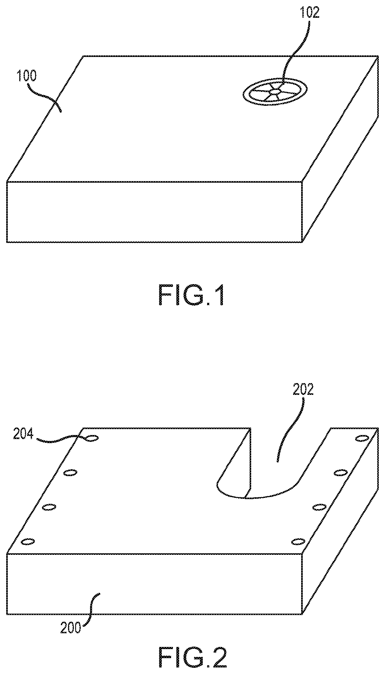
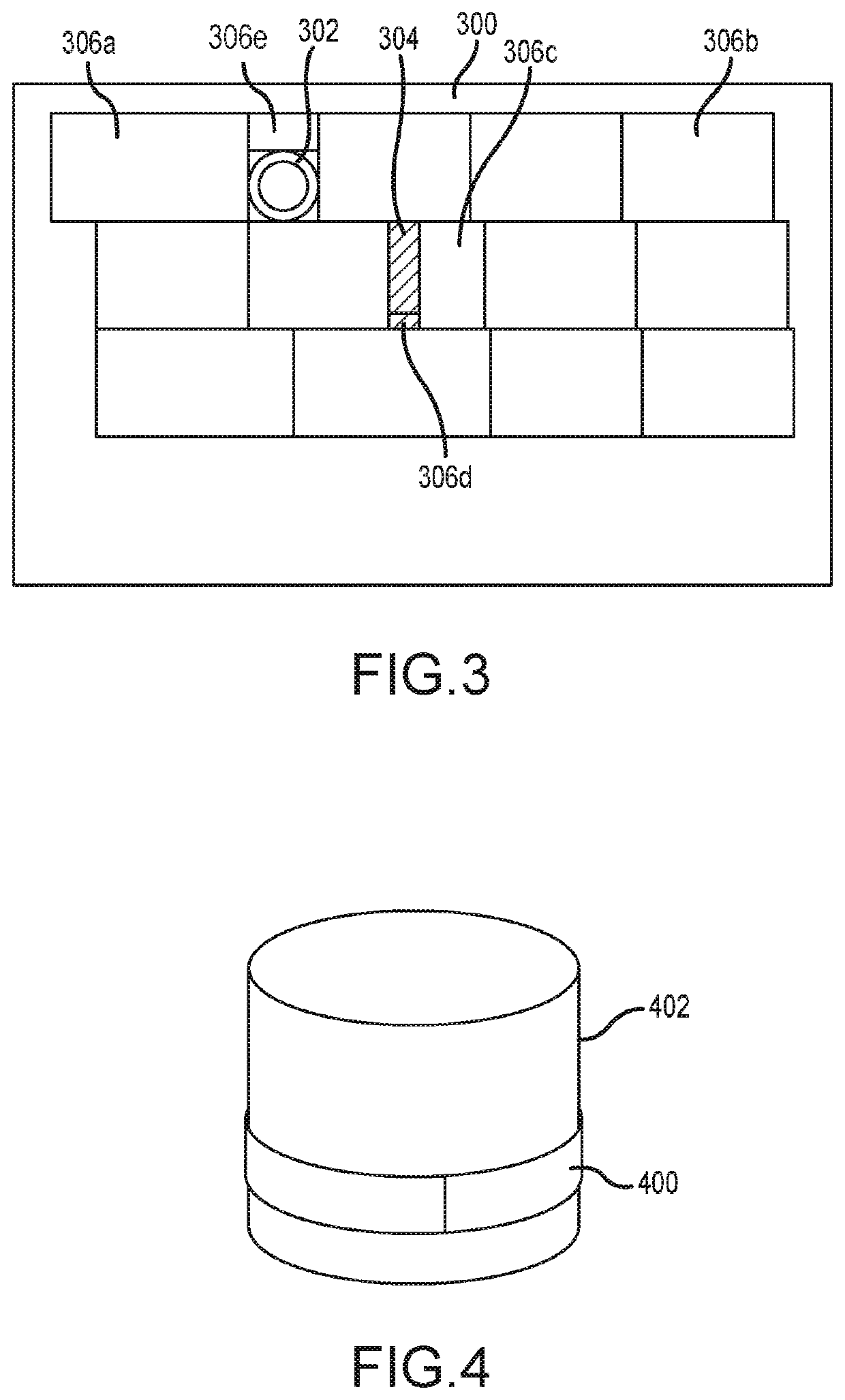
[0028]Embodiments of the invention relate to an insulation and to insulation systems for pipes, storage tanks, and vessels. The insulation systems described herein utilize at least one layer of aerogel insulation to provide thermal and / or acoustic insulation. Aerogels, as described herein, include porous ultralight materials derived from gels, where a liquid component of the gel...


PUM

PropertyMeasurementUnit
thicknessaaaaaaaaaa
thicknessaaaaaaaaaa
thickaaaaaaaaaa

Abstract

An insulation product for a pipe or vessel having at least one aerogel insulation layer, an additional insulation layer positioned around the at least one aerogel insulation layer, and a protective cladding layer surrounding the at least one aerogel insulation layer and the additional insulation layer.

Description

CROSS REFERENCE TO RELATED APPLICATIONS[0001]This application is a division of pending U.S. application Ser. No. 15 / 586,082 filed May 3, 2017, the entire disclosure of which is hereby incorporated by reference herein for all purposes.BACKGROUND OF THE INVENTION[0002]Industrial tanks and vessels used for cryogenic applications are typically insulated by exterior applied insulations, such as cellular glass or PIR foam combined with one or more vapor barrier layers. In applications where higher performance and lower boil off are desired, storage tanks are often constructed as double wall vessels. Typically, in such applications the annulus space is filled with MLI, expanded perlite, or JM Cryolite® insulation, sealed, and then evacuated. Up to 20% of the cryogenic piping at LNG facilities that export products have requirements to meet certain noise standards. The compressors used in the liquefaction process generate loud noise that is radiated along all the pipes connected to the compr...

Claims


Application Information

Patent Timeline
Patent Type & Authority Applications(United States)
IPC IPC(8): F17C13/00F16L59/14B32B15/082B32B1/08B32B5/18B32B3/14F16L59/08
CPCB32B2266/02F16L59/08F17C2203/0325F16L59/028F17C13/001B32B3/14F16L59/141F17C2205/00B32B5/18F17C2203/0308B32B15/082B32B2597/00B32B2307/7246F17C2209/22B32B2307/304B32B1/08F17C2203/0329B32B2266/057B32B27/302B32B2307/732B32B15/20B32B5/16B32B27/14B32B15/043B32B27/08B32B27/304B32B15/18B32B27/18B32B2264/108B32B27/36B32B2255/20B32B2307/414B32B3/266B32B27/32B32B11/048B32B2307/546B32B11/046B32B2255/102B32B27/34B32B2307/412B32B3/20B32B7/08B32B2307/554B32B5/32B32B27/322B32B7/12B32B2266/126B32B2264/102B32B5/30B32B2260/025B32B2255/06B32B2262/0276B32B2266/0214B32B2255/205B32B2270/00B32B2307/10B32B2264/101B32B15/085B32B2260/046B32B3/08B32B2262/12B32B2419/00B32B17/068
Inventor FAY, RALPH MICHAELKORAVOS, JASON J.KOPP, DENNIS A.
Owner JOHNS MANVILLE CORP
Why Eureka
Try Eureka