

Coil component
- Summary
- Abstract
- Description
- Claims
- Application Information
AI Technical Summary
Benefits of technology
Problems solved by technology
Method used
Image

Examples
first embodiment
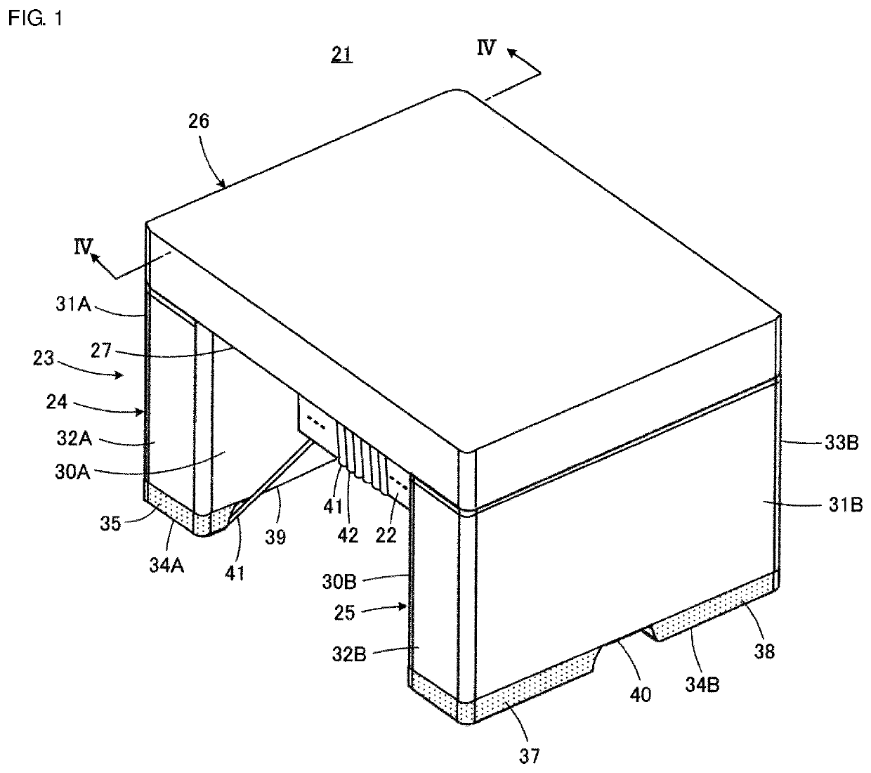
[0022]A coil component 21 according to the present disclosure will be described with reference to FIG. 1 to FIG. 4. The coil component 21 illustrated forms a common mode choke coil.
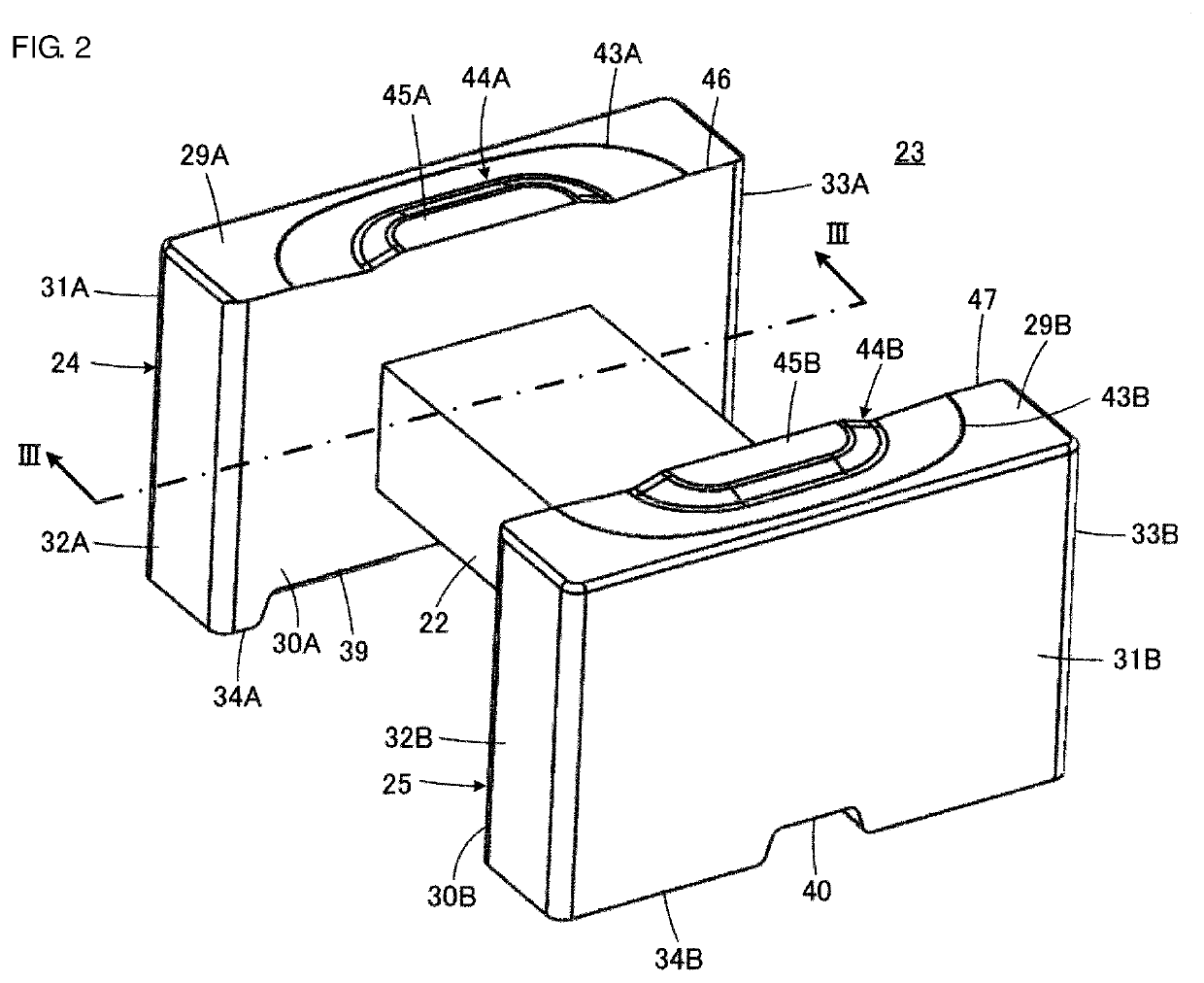
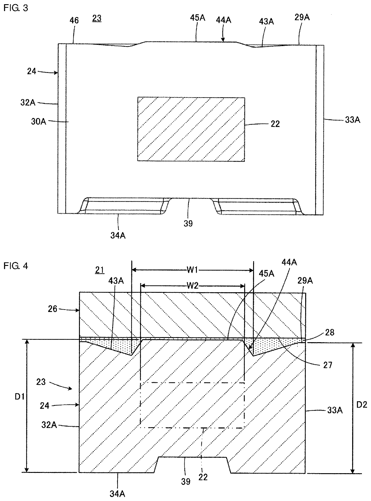
[0023]The coil component 21 includes a winding core 23 that includes a winding core portion 22. The winding core 23 includes a first flange portion 24 and a second flange portion 25 that are disposed on corresponding end portions of the winding core portion 22 and that are opposite each other in the axial direction.
[0024]The coil component 21 also includes a plate core 26. The plate core 26 has a main surface 27 that faces the winding core portion 22, the first flange portion 24, and the second flange portion 25 of the winding core 23, extends between the first flange portion 24 and the second flange portion 25, and is secured to the winding core 23 by using adhesive 28 (see FIG. 4). For example, the adhesive 28 is applied between the plate core 26 and the first flange portion 24 and between the plate cor...
second embodiment
[0051]A coil component 21a according to the present disclosure will now be described with reference to FIG. 5. FIG. 5 is a sectional view of a combination of a winding core 23a and a plate core 26a and corresponds to FIG. 4. In FIG. 5, components corresponding to the components illustrated in FIG. 4 are designated by like reference characters, and a duplicated description is omitted.
[0052]The second embodiment is characterized in that the plate core 26a has a protrusion 48A. This is more specifically described for the structure of the first flange portion 24 illustrated in FIG. 5. The protrusion 48A is formed on the main surface 27 of the plate core 26a in a region in which the recessed portion 43A on the upper surface 29A of the first flange portion 24 faces the main surface 27 of the plate core 26a.
[0053]The protrusion 48A enables effects similar to the effects of the protrusion 44A and the protrusion 44B to be achieved. More specifically, the protrusion 48A inside the recessed p...
PUM
 Abstract
Description
Claims
Application Information