
System and method for increasing coverage of an area captured by an image capturing device

a technology of image capturing and coverage, applied in the field of image manipulation, can solve the problems of unsatisfactory effect of captured imagery, excessive use of processing resources and latency, and inability to achieve optimal correction, so as to achieve the effect of effectively addressing the undesirable rotational alignment of the camera and increasing the overall continuous coverage of the area

Pending Publication Date: 2020-06-25
ELBIT SYST ELECTRO OPTICS ELOP
View PDF0 Cites 0 Cited by
  • Summary
  • Abstract
  • Description
  • Claims
  • Application Information

AI Technical Summary

Benefits of technology

The patent proposes using the movement of the platform on which the image capturing device is mounted to improve the alignment of cameras and increase the coverage of the area captured by the device.

Problems solved by technology

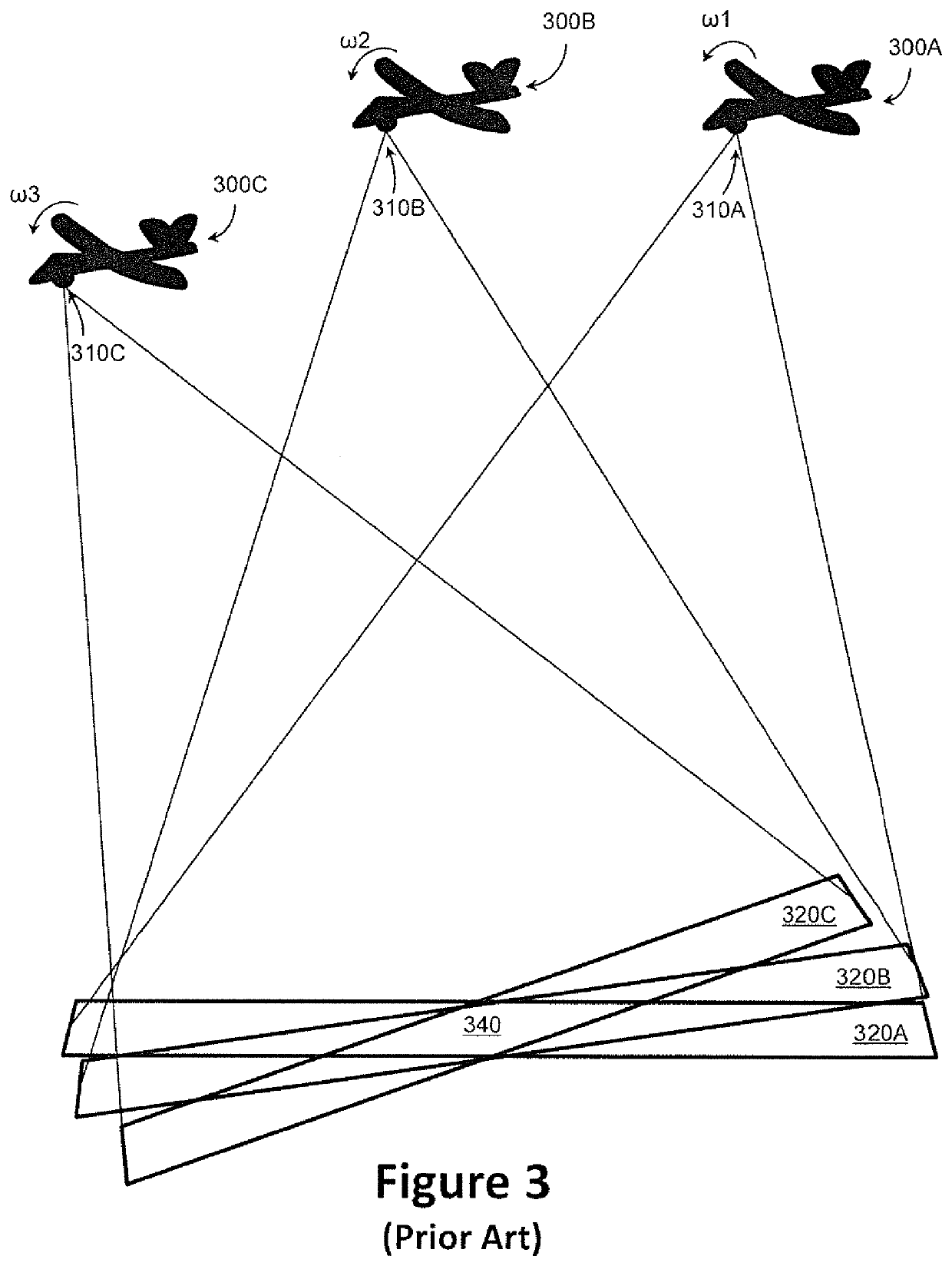
One of the challenges of WAMI sensing is dealing with the non-stationary nature of the aerial platform holding the image capturing device.
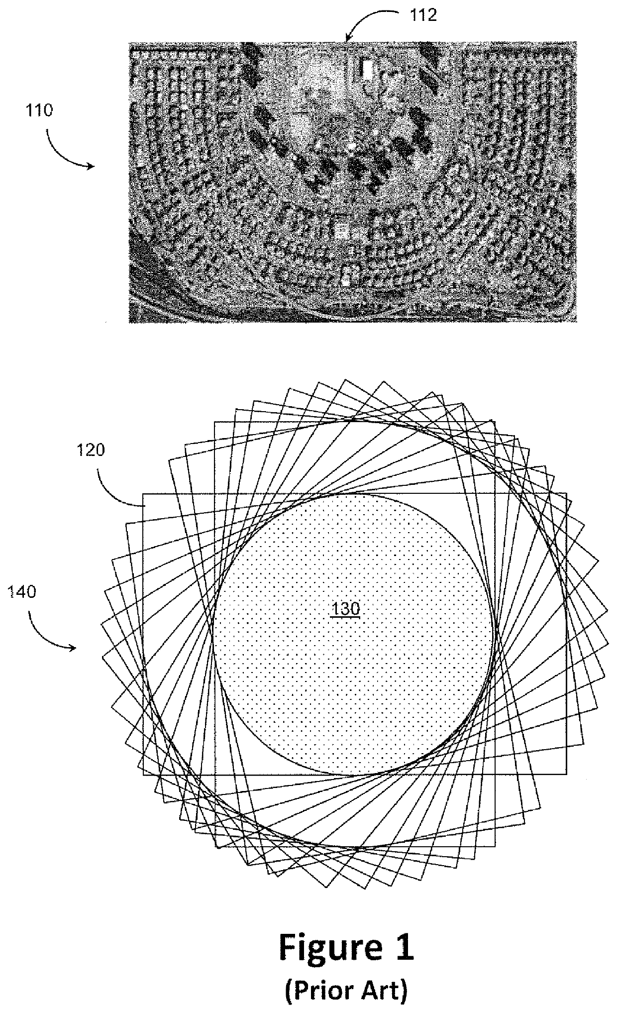
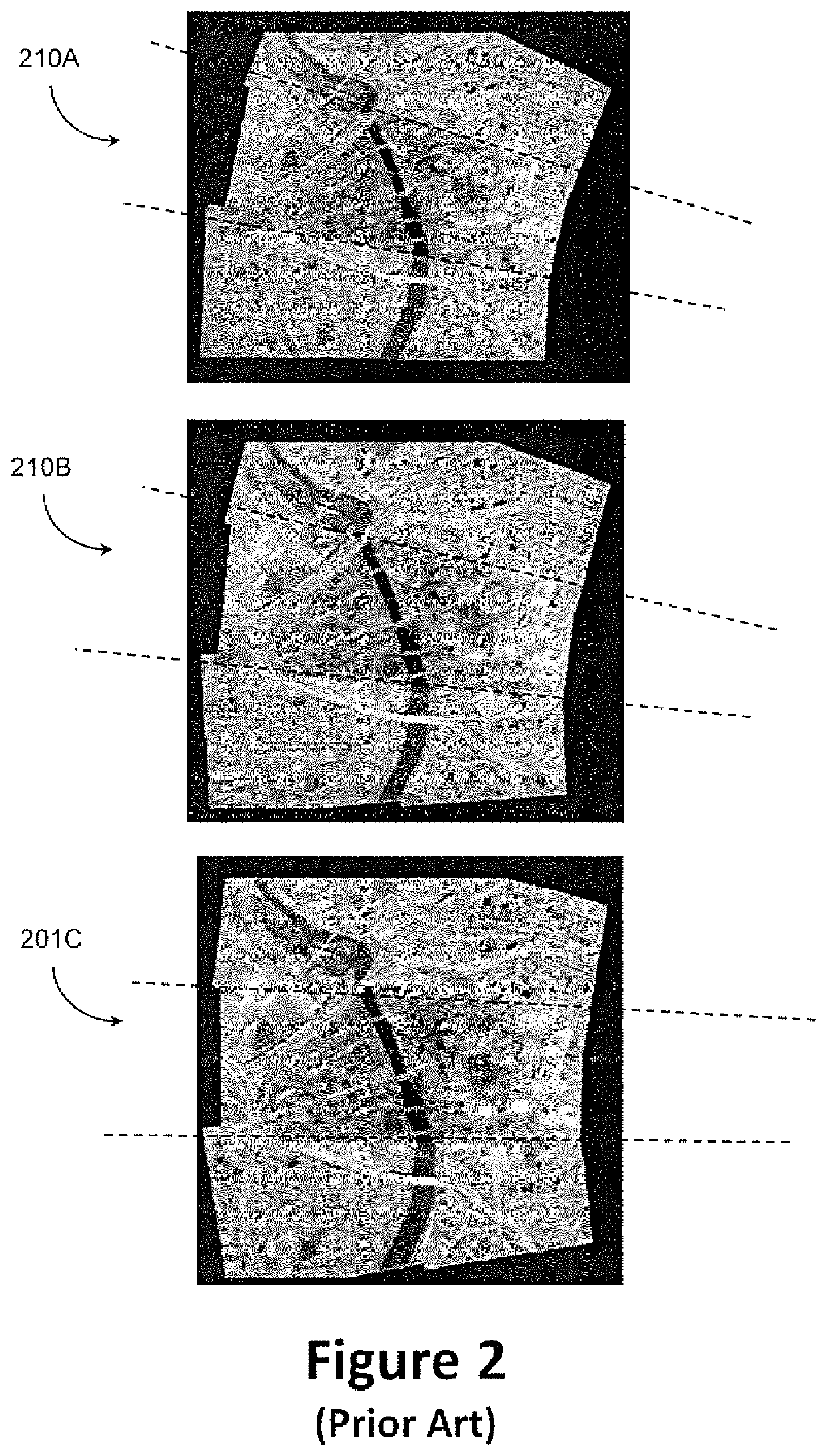
This leads to the undesirable effect of the captured imagery to be constantly rotated along an axis associated with the circular pattern of the aerial vehicle.
The main drawbacks for the aforementioned method is the excessive use of processing resources as well as latency due to the heavy amount of data that is needed to process.
Yet another drawback is that carrying out the compensation of the mis-orientation post capturing does not yield optimal correction as the capturing has already occurred and missing pixels (of areas not covered in the capturing) cannot be recovered.

Method used


Image

  • System and method for increasing coverage of an area captured by an image capturing device
  • System and method for increasing coverage of an area captured by an image capturing device
  • System and method for increasing coverage of an area captured by an image capturing device

Examples


Embodiment Construction

[0030]With specific reference now to the drawings in detail, it is stressed that the particulars shown are for the purpose of example and solely for discussing the preferred embodiments of the present invention, and are presented in the cause of providing what is believed to be the most useful and readily understood description of the principles and conceptual aspects of the invention. In this regard, no attempt is made to show structural details of the invention in more detail than is necessary for a fundamental understanding of the invention. The description taken with the drawings makes apparent to those skilled in the art how the several forms of the invention may be embodied in practice.

[0031]Before explaining the embodiments of the invention in detail, it is to be understood that the invention is not limited in its application to the details of construction and the arrangement of the components set forth in the following descriptions or illustrated in the drawings. The inventi...


PUM


Abstract

A system and a method of increasing an area continuously captured by an image capturing device directed at said area are provided herein. The method may include the following steps: directing said image capturing device at said area in a specified image orientation; receiving momentary orientation measurements of said image capturing device; calculating in real-time, based on said measurements, a shift in orientation of said image capturing device relative to said specified image orientation; providing instructions for rotation in real-time of said image capturing device, to compensate for said shift; and rotating, using a rotation mechanism, said image capturing device based on said instructions, wherein the image capturing device is mounted on a non-stationary platform moving in a periodic pattern.

Description

FIELD OF THE INVENTION[0001]The present invention relates generally to the field of platform-mounted image capturing devices, and more particularly to image manipulations applied on same.BACKGROUND OF THE INVENTION[0002]Prior to the background of the invention being set forth, it may be helpful to provide definitions of certain terms that will be used hereinafter.[0003]The term Wide-Area-Motion-Imagery (WAMI) as used herein is defined as video capturing of an area the size of a town or city. It is a system that uses one or more cameras mounted on some form of a gimbal on an aircraft or blimp to capture a very large area on the ground, from about once every second up to several times per second.[0004]The term “temporary coverage” as used herein is the area covered by an image capturing device on an aerial vehicle flying in a periodic flight pattern over a period of time which is a fraction of the time required for the aircraft to complete its periodic flight pattern. The temporary co...

Claims


Application Information

Patent Timeline
Patent Type & Authority Applications(United States)
IPC IPC(8): H04N5/232G06T7/80H04N17/00
CPCH04N17/002G06T7/80H04N5/23283G03B15/006H04N23/58H04N23/698H04N23/686
Inventor BINDER, SHALOMAVISHAY, NACHUMFREIMAN, DOVPAYKIN, YOTAM
Owner ELBIT SYST ELECTRO OPTICS ELOP
Learn More