
Motor function neural control interface for spinal cord injury patients

a technology for spinal cord injury and motor function, applied in the field of motor function neural control interface for spinal cord injury patients, can solve the problems of patient assistance devices that cannot replicate the biological motor function lost, patient cannot perceive the touch sense, and the patient cannot receive feedback

Active Publication Date: 2020-07-02
BATTELLE MEMORIAL INST
View PDF0 Cites 12 Cited by
  • Summary
  • Abstract
  • Description
  • Claims
  • Application Information

AI Technical Summary

Benefits of technology

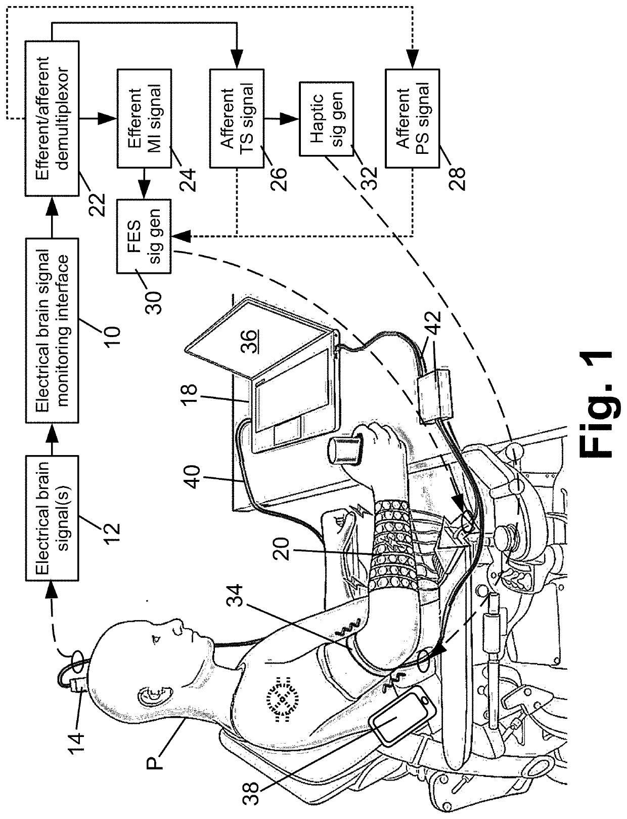
The patent describes an apparatus and method for assisting patients with spinal cord injuries. The apparatus includes an electrical brain signal monitoring interface, a functional electrical stimulation (FES) device, an electronic processor, and a non-transitory storage medium. The electronic processor receives the electrical brain signals and demultiplexes them into an efferent motor intention signal and an afferent sensory signal. The FES device then controls the paralyzed portion of the patient by applying FES to it based on the efferent motor intention signal. The method involves receiving the electrical brain signals, demultiplexing them, and controlling the FES device to control the paralyzed portion of the patient. The apparatus and method can help improve the quality of life for patients with spinal cord injuries.

Problems solved by technology

However, these patient assistance devices do not replicate the biological motor function lost due to the paralysis.
Although a BCI / FES device system can mimic thought-driven motor control, a difficulty remains in terms of feedback to the patient.
In particular, the patient cannot perceive the touch sense due to the functionally complete cervical SCI.
However, this approach has some disadvantages.
Additionally, the patient has had long years of developing motor-sensory feedback based on the touch sense, and it can be difficult for the patient to make the transition to relying upon the different approach of employing visual feedback in a gripping or other motor operation.

Method used


Image

  • Motor function neural control interface for spinal cord injury patients
  • Motor function neural control interface for spinal cord injury patients
  • Motor function neural control interface for spinal cord injury patients

Examples


Embodiment Construction

[0022]A more complete understanding of the methods and apparatuses disclosed herein can be obtained by reference to the accompanying drawings. These figures are merely schematic representations based on convenience and the ease of demonstrating the existing art and / or the present development, and are, therefore, not intended to indicate relative size and dimensions of the assemblies or components thereof.

[0023]Although specific terms are used in the following description for the sake of clarity, these terms are intended to refer only to the particular structure of the embodiments selected for illustration in the drawings, and are not intended to define or limit the scope of the disclosure. In the drawings and the following description below, it is to be understood that like numeric designations refer to components of like function.

[0024]As used herein, the “motor cortex” encompasses all components of the sensorimotor cortex, including sub-regions such as those designated as the prim...


PUM


Abstract

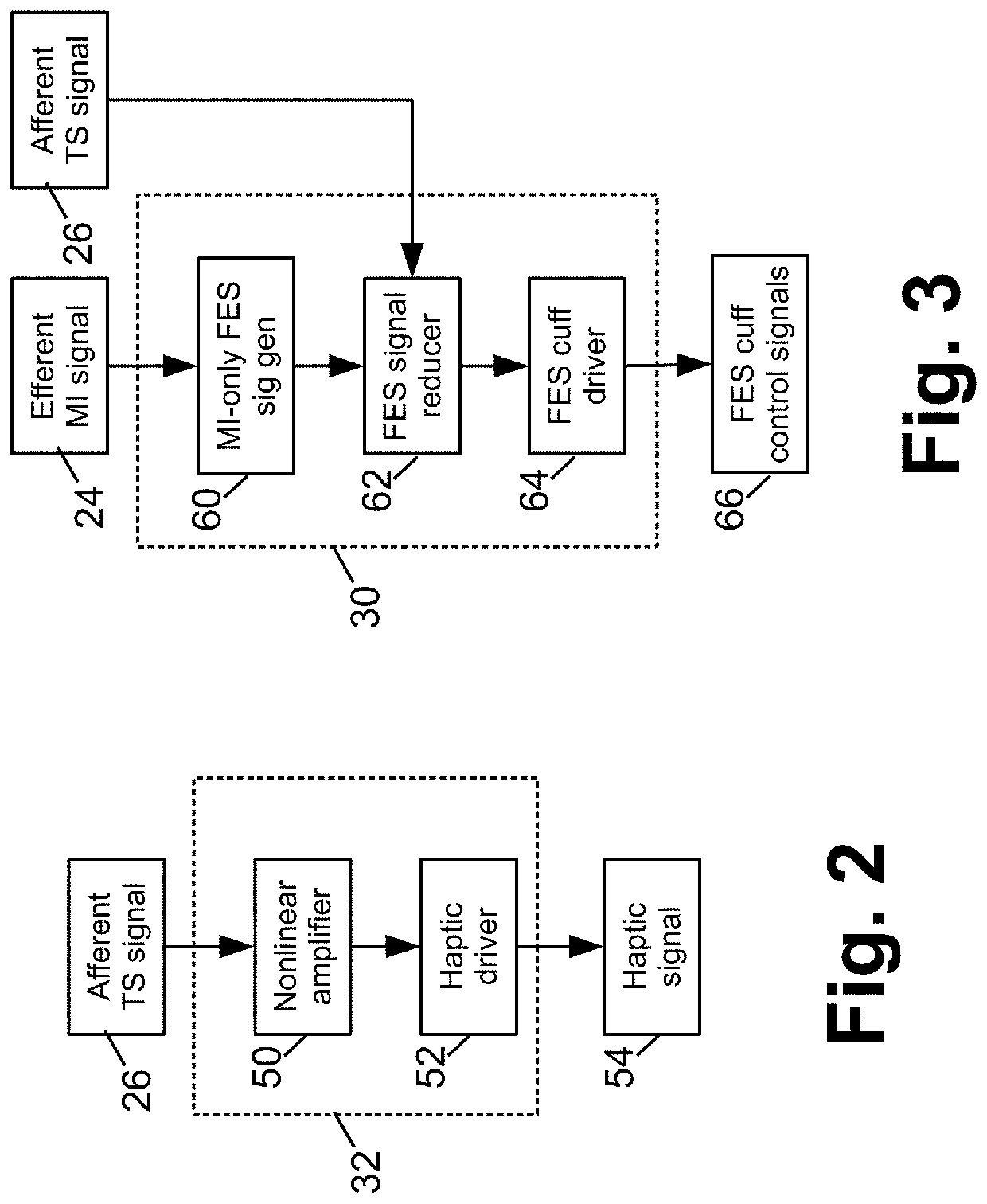
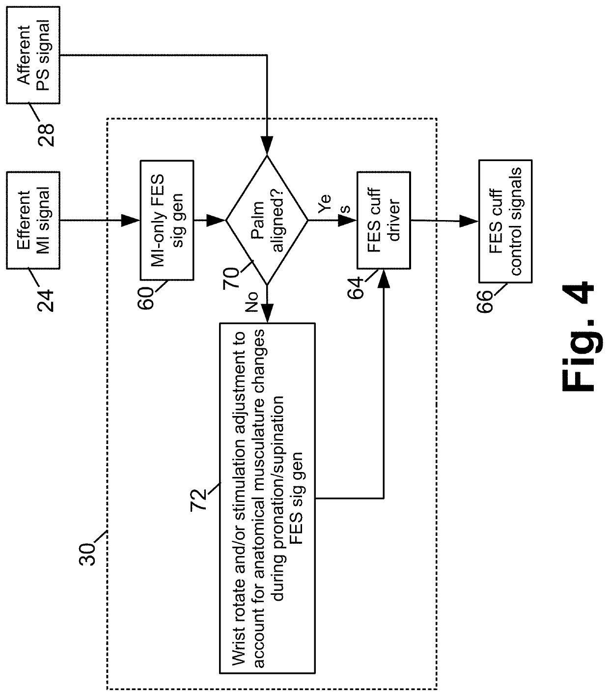
At least one electrical brain signal is received from a patient and is demultiplexed into an efferent motor intention signal and at least one afferent sensory signal (such as an afferent touch sense signal and / or an afferent proprioception signal). A functional electrical stimulation (FES) device is controlled to apply FES to control a paralyzed portion of the patient that is paralyzed due to a spinal cord injury of the patient. The controlling of the FES device is based on at least the efferent motor intention signal. A demultiplexed afferent touch sense signal may be used to control a haptic device. The afferent sensory signal(s) may be used to adjust the FES control.

Description

[0001]This application claims the benefit of provisional application No. 62 / 798,648 filed Jan. 30, 2019. This application claims the benefit of provisional application No. 62 / 787,060 filed Dec. 31, 2018. Provisional application No. 62 / 798,648 filed Jan. 30, 2019 is incorporated herein by reference in its entirety. Provisional application No. 62 / 787,060 filed Dec. 31, 2018 is incorporated herein by reference in its entirety.BACKGROUND[0002]The following relates to the medical arts, neural-control interface arts, brain-computer interface arts, motor function neural control interface arts, functional electrical neuro-motor stimulation arts, neurosensory function assessment and control interface arts, and related arts, and to apparatuses and methods employing same for providing motor functionality to patients with spinal cord injuries.[0003]Over 100,000 individuals in the United States currently live with a cervical spinal cord injury (SCI), in which the cervical spinal cord is partiall...

Claims


Application Information

Patent Timeline
Patent Type & Authority Applications(United States)
IPC IPC(8): A61N1/36A61N1/02
CPCA61N1/36003G06N3/02A61N1/36031A61N1/025
Inventor GANZER, PATRICKCOLACHIS, SAMUELSCHWEMMER, MICHAELFRIEDENBERG, DAVID A.SHARMA, GAURAV
Owner BATTELLE MEMORIAL INST
Learn More