Eureka AIR delivers breakthrough ideas for toughest innovation challenges, trusted by R&D personnel around the world.

Method of manufacturing fastening portion of anisogrid composite structure

Inactive Publication Date: 2020-07-02
AGENCY FOR DEFENSE DEV
View PDF0 Cites 2 Cited by
  • Summary
  • Abstract
  • Description
  • Claims
  • Application Information

AI Technical Summary

Benefits of technology

The patent text describes a method for making a rigid composite structure. The method allows the designer to control the rigidity of the structure by varying the angles of the plies of fiber and the percentage of lamination. This results in a strong supporting force in different directions, including axial load. The manufacturing process is simple, and there is no need for additional steps to fasten the structure. The method also ensures that the rigidity is maintained even after curing. Additionally, the method minimizes deformation of the cylinder after curing and removes defects caused by shrinkage during curing.

Problems solved by technology

Therefore, there is a limit to manufacture such an anisogrid composite structure in a large size at a single time.
However, a conventional fastening portion of the anisogrid composite structure manufactured by performing wet filament winding has problems in that fibers to be laminated have a predetermined orientation due to characteristics of the process, and change in the ply angle is limited.
The conventional technique has a problem in that a step is formed at a joint of the fastening portion.
Such a step degrades the stability of the structure.

Method used


Image

  • Method of manufacturing fastening portion of anisogrid composite structure
  • Method of manufacturing fastening portion of anisogrid composite structure
  • Method of manufacturing fastening portion of anisogrid composite structure

Examples


Embodiment Construction

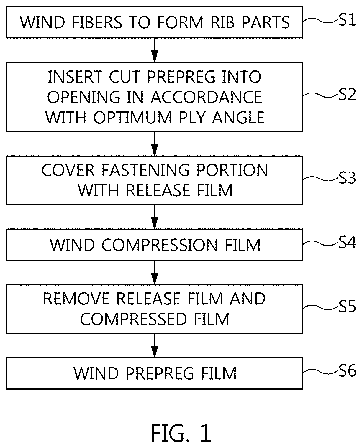
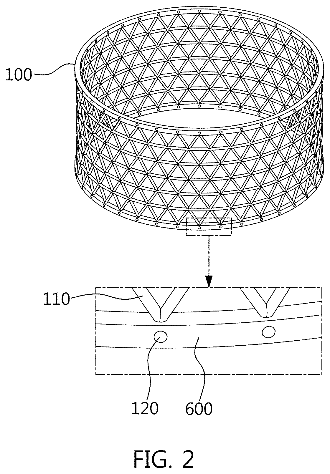
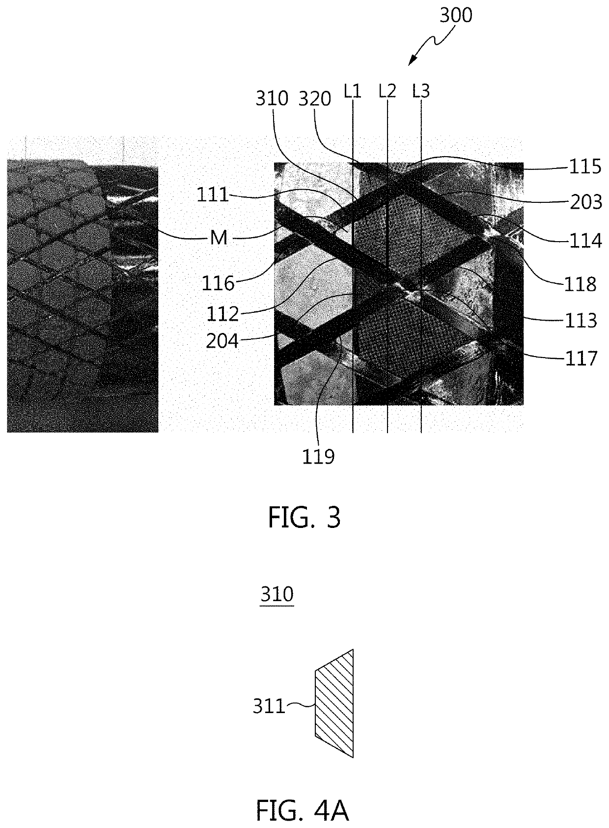
[0052]Hereinbelow, an embodiment of the present invention will be described in detail with reference to the accompanying drawings.

[0053]Reference will now be made in detail to exemplary embodiments of the present invention, specific examples of which are illustrated in the accompanying drawings and described below, since the embodiments of the present invention can be variously modified in many different forms. While the present invention will be described in conjunction with the exemplary embodiments thereof, it is to be understood that the present description is not intended to limit the present invention to those exemplary embodiments. On the contrary, the present invention is intended to cover not only the exemplary embodiments, but also various alternatives, modifications, equivalents, and other embodiments that may be included within the spirit and scope of the present invention as defined by the appended claims.

[0054]The same reference numerals will be used throughout the dra...


PUM

PropertyMeasurementUnit
Angleaaaaaaaaaa
Pressureaaaaaaaaaa
Shapeaaaaaaaaaa

Abstract

A method of manufacturing a fastening portion of an anisogrid composite structure includes winding the fibers to form multiple rib parts of the fastening portion configured by winding fibers on a mold, cutting a prepreg into a shape corresponding to a shape of an opening defined by the multiple ribs, inserting the cut prepreg into the corresponding opening, covering the fastening portion with a release film, and winding a compression film on the release film to apply pressure to the fastening portion.

Description

CROSS REFERENCE TO RELATED APPLICATION[0001]This application claims the benefit of Korean Patent Application No. 10-2018-0172458, filed Dec. 28, 2018, which is hereby incorporated by reference in its entirety into this application.BACKGROUND OF THE INVENTION1. Technical Field[0002]The present invention relates to a method of manufacturing a fastening portion of an anisogrid composite structure and, more particularly, to a method of manufacturing a fastening portion of an anisogrid composite structure, the fastening portion having no depression and step.2. Description of Related Art[0003]An anisogrid composite structure achieves weight reduction of about 20% to 50% compared with a metal structure designed to withstand the same structural load.[0004]Because of this advantage, the anisogrid composite structure finds application in large structures such as aircraft, launch vehicles, and missiles.[0005]A shape of the anisogrid composite structure is defined by a shape of a mold on which ...

Claims


Application Information

Patent Timeline
IPC IPC(8): B29C53/56B29C70/34
CPCB29C70/34B29C53/566B29C70/32B29C70/205B29L2028/00B29D28/00B29L2031/737B29C37/0075B29C70/382B29C70/545
Inventor LEE, YEON-GWANKIM, JAE-YOUNGKIM, HONG-ILLEE, DAE-OEN
Owner AGENCY FOR DEFENSE DEV
Why Eureka
Eureka Blog
Learn More